1. Introduction
This user manual provides essential information for the proper installation, operation, and maintenance of the IBXDTUVJ IL-NT-PRAMAC AC03 Generator Controller. This module is designed to provide automatic transfer switch (ATS) functionality, protection, and control for generator systems. Please read this manual thoroughly before attempting any installation or operation.
2. Product Overview
The IL-NT-PRAMAC AC03 is an advanced digital control system featuring a display module for monitoring and managing generator operations. It integrates various functions for reliable generator performance and protection.

Figure 2.1: Front view of the AC03 controller, showing the display screen and control buttons.

Figure 2.2: Angled front view of the AC03 controller, highlighting the bottom connection terminals.
3. Setup and Installation
Proper installation is crucial for the safe and effective operation of the AC03 controller. Ensure all power sources are disconnected before beginning installation.
3.1 Mounting
The controller is designed for use on a flat surface within a Type 1 enclosure. Secure the module using appropriate fasteners to prevent vibration and ensure stability.
3.2 Electrical Connections
Refer to the wiring diagram and terminal labels on the rear of the unit for correct electrical connections. Use copper conductors only. Ensure all connections are secure and tightened to the specified torque values (refer to separate installation instructions for detailed torque specifications).
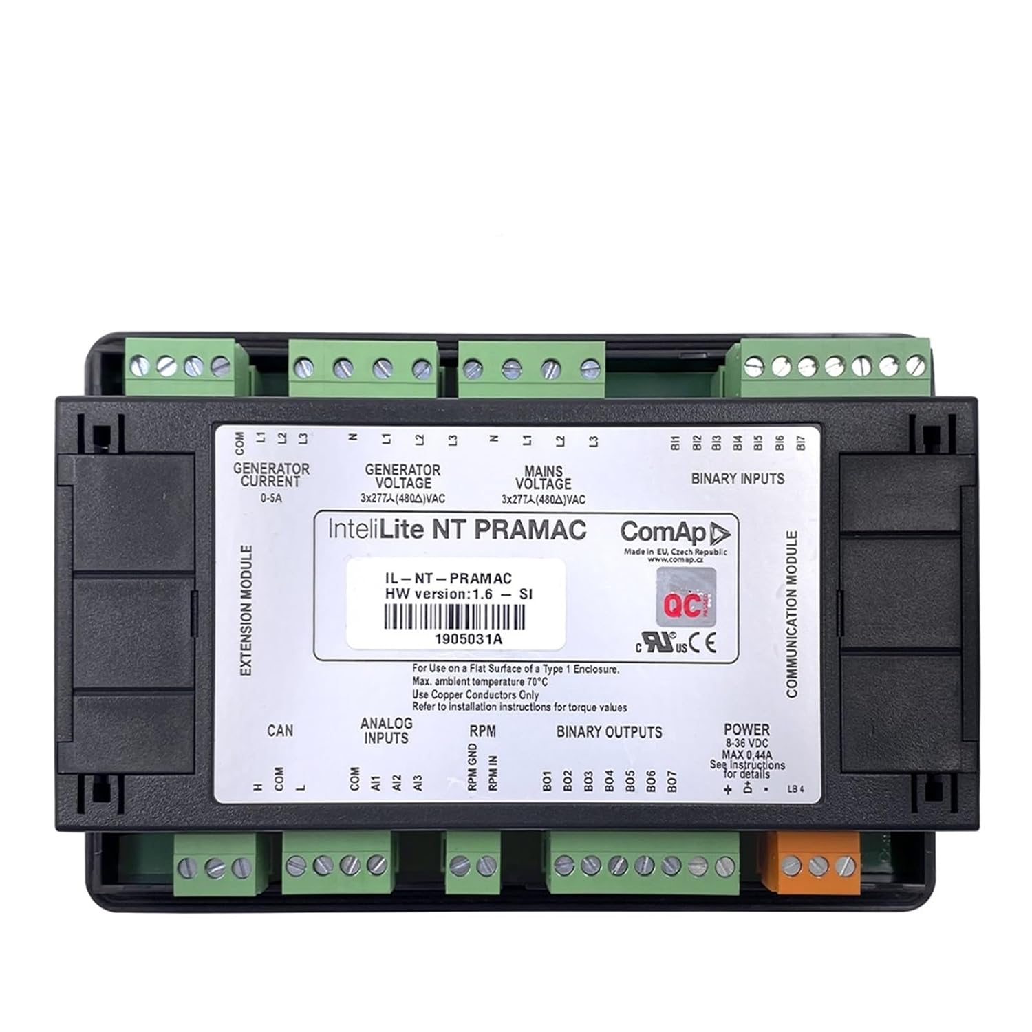
Figure 3.1: Rear view of the AC03 controller, displaying various input/output terminals, power connections, and communication ports. Key labels include 'GENERATOR CURRENT 0-5A', 'GENERATOR VOLTAGE 3x277A/480VAC', 'MAINS VOLTAGE 3x277A/480VAC', 'BINARY INPUTS', 'ANALOG INPUTS', 'RPM', 'BINARY OUTPUTS', and 'POWER 8-36 VDC'.
- Power Supply: The unit requires a power input of 8-36 VDC. Connect the power supply to the designated terminals.
- Generator Voltage/Current: Connect the generator voltage and current sensing lines to the appropriate terminals as indicated. The module supports 3x277A/480VAC for voltage and 0-5A for current.
- Mains Voltage: Connect the mains (utility) voltage sensing lines. The module supports 3x277A/480VAC.
- Binary Inputs: Connect external switches or sensors to the binary input terminals for various control and monitoring functions.
- Analog Inputs: Connect analog sensors (e.g., for oil pressure, coolant temperature) to the analog input terminals.
- RPM Input: Connect the engine RPM signal to the designated terminal.
- Binary Outputs: These terminals provide control signals for external devices such as contactors, fuel pumps, or alarms.
- CAN Bus: The module includes a CAN bus interface for communication with other compatible devices.
3.3 Environmental Considerations
The maximum ambient temperature for operation is 70°C. Ensure the installation location provides adequate ventilation and does not exceed this temperature limit.
4. Operating Instructions
The AC03 controller features an intuitive interface for monitoring and controlling your generator.
4.1 Control Panel Layout

Figure 4.1: Angled view of the AC03 controller, showing the display and various control buttons.
- Display Screen: Shows operational parameters, status messages, and fault indications.
- MODE Buttons (Left/Right Arrows): Used to navigate through different display screens and menus.
- START Button (Green): Initiates the generator start sequence.
- STOP Button (Red): Initiates the generator stop sequence.
- FUEL PUMP Button: Manually controls the fuel pump.
- FAULT RESET Button: Resets active fault conditions after the cause has been addressed.
- PAGE Buttons (Up/Down Arrows): Used to scroll through information on the display or navigate within menus.
4.2 Basic Operation
- Power On: Ensure the controller is powered correctly (8-36 VDC). The display should illuminate.
- Monitoring: Use the MODE buttons to cycle through various operational screens, displaying parameters such as generator voltage, current, frequency, engine RPM, oil pressure, and coolant temperature.
- Starting the Generator: Press the START button. The controller will initiate the pre-heat (if configured) and cranking sequence.
- Stopping the Generator: Press the STOP button. The controller will initiate the cool-down (if configured) and stop sequence.
- Fault Handling: If a fault occurs, the display will show an error message. Address the underlying issue, then press the FAULT RESET button to clear the alarm.
5. Maintenance
The AC03 controller is designed for minimal maintenance. However, periodic checks are recommended to ensure optimal performance.
- Cleaning: Keep the display and buttons clean using a soft, dry cloth. Do not use abrasive cleaners or solvents.
- Connection Checks: Periodically inspect all wiring connections for tightness and signs of corrosion.
- Firmware Updates: Consult the manufacturer's website or support for information on available firmware updates.
6. Troubleshooting
This section provides basic troubleshooting steps for common issues.
| Problem | Possible Cause | Solution |
|---|---|---|
| Controller does not power on | No power supply; Incorrect wiring; Blown fuse | Check 8-36 VDC power supply; Verify wiring connections; Inspect and replace fuse if necessary. |
| Generator fails to start | Low fuel; Low battery; Engine fault; Incorrect settings | Check fuel level; Check battery voltage; Investigate engine fault codes; Verify controller settings. |
| Display shows an error message | Active fault condition | Identify the fault code/message; Address the underlying issue; Press FAULT RESET. |
For complex issues or persistent problems, contact technical support.
7. Specifications
| Feature | Specification |
|---|---|
| Product Model | AC03 |
| Manufacturer's Model Number | IBXDTUVJ |
| Manufacturer | IBXDTUVJ |
| Power Input | 8-36 VDC |
| Generator Voltage Input | 3x277A/480VAC |
| Mains Voltage Input | 3x277A/480VAC |
| Generator Current Input | 0-5A |
| Max. Ambient Temperature | 70°C |
| Dimensions (Package) | 3 x 2 x 1 cm |
| Weight (Package) | 50 g |
| Country of Origin | China |
8. Warranty and Support
Information regarding product warranty and technical support is typically provided with the product packaging or available on the manufacturer's official website. Please refer to those resources for detailed warranty terms and contact information for support.