
1. Introduction
The PLPFUDVDZZ SCN76 Series Digital Counter is a 6-digit industrial counter designed for precise measurement applications, such as wire length measurement. It features an encoder input and relay contact signal output, making it suitable for various industrial control systems. This manual provides detailed instructions for the installation, operation, and maintenance of your SCN76 digital counter.
2. Product Features
- 6-digit display for accurate counting.
- Supports contact signal or pulse signal input.
- Equipped with relay contact signal output.
- Compact design for easy integration.
- User-friendly interface for straightforward operation.
- Mechanical counting mechanism for reliability.
3. Components Overview
Familiarize yourself with the main components and controls of the SCN76 digital counter as illustrated below:

Figure 3.1: SCN76 Digital Counter Front Panel. This image displays the front panel of the SCN76 counter, highlighting key elements such as the display value, preset value, J1 and J2 indicators, and control buttons (SET, Move Key, ARST/Exit Key). The instrument model "SCN76" is also visible.
- Display Value: Shows the current count.
- Preset Value: Displays the target value for relay activation.
- J1 Indicator: Illuminates when Relay Output 1 is active.
- J2 Indicator: Illuminates when Relay Output 2 is active.
- SET Button: Used to confirm settings or enter the menu (press and hold for three seconds).
- Move Key (>>): Used to change the position of the digit being edited or to navigate menu options.
- ARST / Exit Key: Used to adjust numbers, reset the counter, or exit menu settings.
4. Technical Specifications
The following table outlines the technical specifications for the SCN76 Digital Counter:
Figure 4.1: SCN76 Digital Counter Key Specifications. This image provides a summary of the SCN76's product model, counting range, input signal type, output signal type, and working power supply.
| Specification | Value |
|---|---|
| Product Model | SCN76 |
| Counting Range | 0-999999 (6-digit) |
| Input Signal | Contact signal or Pulse signal |
| Output Signal | Relay contact signal output |
| Working Power Supply | AC220V |
| Item Weight | 10.6 ounces (approx. 300g) |
| Batteries Required | No |
5. Setup and Installation
5.1 Physical Installation
The SCN76 counter is designed for panel mounting. Ensure adequate space and proper ventilation for the unit.
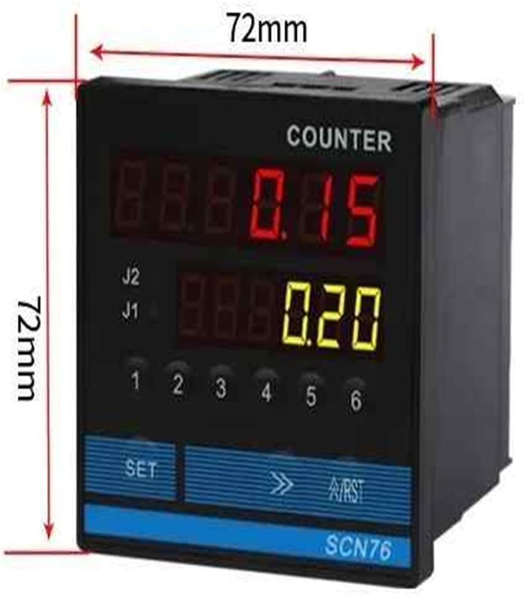
Figure 5.1: SCN76 Digital Counter Dimensions. This image shows the physical dimensions of the SCN76 counter, indicating a width and height of 72mm each.
- Dimensions: The counter measures approximately 72mm x 72mm (width x height). Ensure your panel cutout matches these dimensions.
- Mounting: Secure the counter into the panel cutout using the provided mounting hardware.
5.2 Encoder and Wheel Roller Installation (Optional)
For applications requiring length measurement, an encoder with a wheel roller can be connected to the SCN76 counter.

Figure 5.2: SCN76 Counter Connected to an Encoder and Wheel Roller. This image illustrates the SCN76 digital counter integrated with an external encoder and a measuring wheel, typically used for length or wire measurement applications.

Figure 5.3: Encoder Mounting Bracket. This image shows a short-style mounting bracket for the encoder, with dimensions of 140mm length and 80mm height, including screw mounting holes.

Figure 5.4: Measuring Wheel Specifications. This image details the dimensions of the measuring wheel, indicating a wheel width of 15mm and a depth of 5mm.
- Mount the encoder using a suitable bracket (e.g., 140mm x 80mm short style bracket with screw mounting holes).
- Ensure the measuring wheel (15mm width, 5mm depth) makes firm and consistent contact with the material being measured.
- Connect the encoder output to the appropriate input terminals on the SCN76 counter. Refer to the wiring diagram for specific connections.
5.3 Electrical Wiring
Proper wiring is crucial for safe and correct operation. Refer to the wiring diagram below and ensure all connections are secure.

Figure 5.5: SCN76 Digital Counter Terminal Connections. This image provides a detailed wiring diagram for the SCN76 counter, labeling terminals for working power supply, relay outputs (1 and 2), reset, suspends, signal terminal, common end, and 12V power input.
| Terminal Number(s) | Function |
|---|---|
| 1, 2, 3 | Relay Output 2 (J2) |
| 4, 5, 6 | Relay Output 1 (J1) |
| 6, 7 | Working Power Supply (AC85-265V) |
| 8 | Reset |
| 9 | Suspends (Pause) |
| 10, 11, 12 | Signal Terminal (CP1, CP2, CP3 for encoder input) |
| 13 | Common End (COM) |
| 14 | +12V Power Input (for external sensors/encoders) |
Important: Ensure the power supply matches the specified AC220V. Incorrect voltage can damage the device. Consult a qualified electrician if you are unsure about wiring procedures.
6. Operation
6.1 Power On
Once wired correctly, apply power to the unit. The display will illuminate, showing the current count and preset values.
6.2 Basic Counting
The counter will begin counting based on the input signals received at the signal terminals (CP1, CP2, CP3). The main display shows the accumulated count.
6.3 Setting Preset Values
- Press and hold the SET button for approximately three seconds to enter the menu or setting mode.
- Use the Move Key (>>) to select the digit you wish to change in the preset value.
- Use the ARST button to adjust the numerical value of the selected digit.
- Repeat steps 2 and 3 for all digits of the preset value.
- Press the SET button again to confirm and save the preset value.
- Press the ARST button to exit the setting mode and return to normal operation.
When the display value reaches the preset value, the corresponding relay output (J1 or J2) will activate.
6.4 Resetting the Counter
To reset the current count to zero, briefly press the ARST button during normal operation. Alternatively, a remote reset can be triggered via the dedicated reset terminal (Terminal 8).
7. Maintenance
- Cleaning: Keep the counter's display and housing clean. Use a soft, dry cloth. Avoid abrasive cleaners or solvents.
- Environment: Ensure the operating environment is free from excessive dust, moisture, and corrosive gases.
- Connections: Periodically check all electrical connections for tightness and signs of wear.
- Encoder/Wheel: If using an encoder with a wheel, ensure the wheel is clean and rotates freely. Check for wear on the wheel surface.
8. Troubleshooting
| Problem | Possible Cause | Solution |
|---|---|---|
| Counter does not power on. | No power supply or incorrect voltage. | Check power connections and ensure AC220V is supplied. Verify wiring. |
| Counter not counting. | Incorrect input signal wiring; faulty sensor/encoder; input signal too weak or too fast. | Verify input signal connections (Terminals 10, 11, 12). Test sensor/encoder functionality. Adjust input signal parameters if possible. |
| Relay output not activating. | Preset value not reached; incorrect relay wiring; faulty relay. | Check if the current count has reached the preset value. Verify relay output wiring (Terminals 1-6). Test the relay. |
| Display shows erratic readings. | Electrical noise/interference; loose connections. | Ensure proper grounding. Check all connections for tightness. Shield input cables if necessary. |
9. Warranty and Support
Specific warranty information for the PLPFUDVDZZ SCN76 Digital Counter is not provided in this manual. Please refer to your purchase documentation or contact your retailer for details regarding warranty coverage.
For technical support or inquiries, please contact the manufacturer or your authorized distributor. Ensure you have your product model (SCN76) and purchase details available when seeking support.