1. Introduction
The NYUMMRYT DSP-10 is a multi-function display module designed for diesel generator sets. It provides essential monitoring capabilities, including voltage, current, and frequency, to ensure optimal performance and operational safety of your generator. This manual provides detailed instructions for the installation, operation, and maintenance of the DSP-10 module.

Figure 1: Front angled view of the DSP-10 Multi-Function Display Module. The display shows three segments for readings and buttons for Voltage, Amperage, and Function.
2. Safety Information
Please read and understand all safety instructions before installing or operating the DSP-10 module. Failure to follow these instructions may result in electric shock, fire, serious injury, or property damage.
- Qualified Personnel: Installation and maintenance should only be performed by qualified and authorized personnel.
- Power Disconnection: Always disconnect power from the generator set before performing any installation, wiring, or maintenance.
- Electrical Hazards: This device operates with electrical currents. Exercise extreme caution to avoid electric shock.
- Proper Wiring: Ensure all wiring connections are secure and comply with local electrical codes and standards.
- Environmental Conditions: Do not expose the module to excessive moisture, dust, or extreme temperatures outside its specified operating range.
3. Package Contents
Verify that all items are present and undamaged upon opening the package. If any items are missing or damaged, contact your supplier immediately.
- DSP-10 Multi-Function Display Module
- Mounting Brackets (typically pre-attached or included)
- Terminal Connectors (green, as shown in images)
- User Manual (this document)
4. Setup and Installation
4.1 Mounting the Module
The DSP-10 module is designed for panel mounting. Ensure the mounting hole dimensions are appropriate for the module's size.
- Cut a rectangular opening in the control panel according to the module's dimensions.
- Insert the DSP-10 module into the opening from the front.
- Secure the module using the provided mounting brackets on the sides. Push the brackets firmly until the module is snug against the panel.
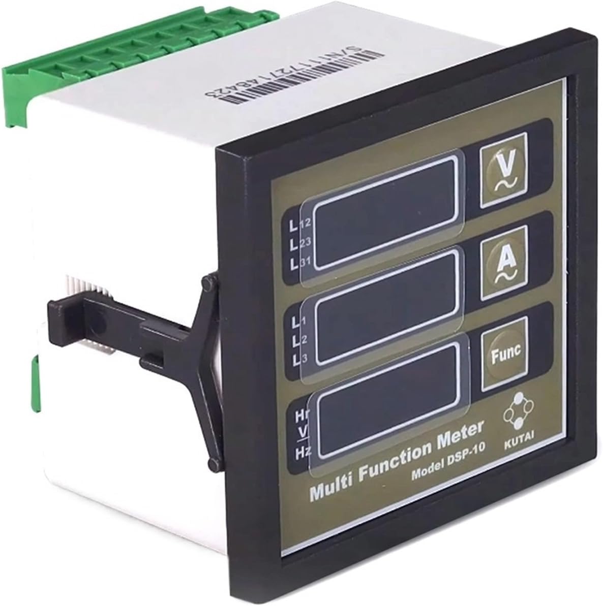
Figure 2: Front view of the DSP-10 module, showing the display and control buttons. The mounting clips are visible on the sides.
4.2 Wiring Connections
Refer to the wiring diagram provided with your generator set and the labels on the back of the DSP-10 module for correct connections. Ensure all power is disconnected before wiring.

Figure 3: Rear view of the DSP-10 module, showing the green terminal blocks for electrical connections. The serial number S/N:111727148423 is visible.
- Power Supply: Connect the module to the appropriate DC power supply (e.g., 12V or 24V DC) as specified by the module's requirements.
- Voltage Inputs: Connect the generator's phase voltages (L1, L2, L3) to the corresponding voltage input terminals.
- Current Transformer (CT) Inputs: Connect the secondary windings of the current transformers to the module's current input terminals (A+, A-). Ensure correct polarity.
- Frequency/Hour Meter Input: Connect the appropriate signal for frequency and hour meter readings.

Figure 4: Detailed rear view of the DSP-10 module, highlighting the DIP switches (J2-8) and the "PROGRAMMER TABLE" for current transformer ratio settings. The serial number S/N:111727148423 is visible.
4.3 CT Ratio Configuration
The DSP-10 module features DIP switches (J2-8) on the rear for configuring the Current Transformer (CT) ratio. Refer to the "PROGRAMMER TABLE" printed on the module to set the correct ratio for your CTs. Incorrect settings will result in inaccurate current readings.
| DIP Switch Setting (1-5) | CT Ratio |
|---|---|
| ON-OFF-OFF-OFF-OFF | 50A |
| OFF-ON-OFF-OFF-OFF | 100A |
| ON-ON-OFF-OFF-OFF | 150A |
| OFF-OFF-ON-OFF-OFF | 200A |
| ... | ... |
| OFF-OFF-OFF-OFF-ON | 1200A |
Note: The exact "PROGRAMMER TABLE" is printed on the back of the DSP-10 module. Always refer to the physical module for accurate settings.
5. Operating Instructions
Once installed and powered, the DSP-10 module will automatically display key generator parameters.
5.1 Display Overview
The front panel features three digital displays and three control buttons:
- Top Display: Typically shows Line-to-Line Voltage (L12, L23, L31).
- Middle Display: Typically shows Line Current (L1, L2, L3).
- Bottom Display: Typically shows Frequency (Hz) or Run Hours (Hr).
5.2 Button Functions
- V (Voltage) Button: Press to cycle through different voltage readings (e.g., L12, L23, L31).
- A (Amperage) Button: Press to cycle through different current readings (e.g., L1, L2, L3).
- Func (Function) Button: Press to cycle through other functions like Frequency (Hz) or accumulated Run Hours (Hr).
The module continuously monitors and displays the selected parameters. No further user interaction is typically required for basic monitoring.
6. Maintenance
The DSP-10 module is designed for minimal maintenance. Regular inspection and cleaning will help ensure its longevity and accurate operation.
- Cleaning: Periodically clean the front panel with a soft, dry cloth. Do not use abrasive cleaners or solvents.
- Inspection: Regularly inspect all wiring connections for tightness and signs of corrosion or damage.
- Environmental Protection: Ensure the module remains protected from excessive dust, moisture, and vibrations.
Note: There are no user-serviceable parts inside the module. Do not attempt to open or repair the unit.
7. Troubleshooting
If you encounter issues with your DSP-10 module, refer to the following common problems and solutions:
| Problem | Possible Cause | Solution |
|---|---|---|
| Module does not power on. | No power supply, incorrect wiring, blown fuse. | Check power connections, verify supply voltage, inspect fuses in the power circuit. |
| Incorrect voltage readings. | Incorrect voltage input wiring. | Verify voltage input connections against the wiring diagram. |
| Incorrect current readings. | Incorrect CT ratio setting, incorrect CT wiring polarity, faulty CT. | Check DIP switch settings for CT ratio (refer to Section 4.3). Verify CT wiring polarity. Test or replace CTs if suspected faulty. |
| Display is blank or flickering. | Unstable power supply, internal fault. | Ensure stable power supply. If problem persists, contact support. |
If the problem cannot be resolved using the above steps, contact NYUMMRYT customer support or a qualified technician.
8. Specifications
The following are the general specifications for the NYUMMRYT DSP-10 Multi-Function Display Module:
- Model: DSP-10
- Brand: NYUMMRYT
- Item Weight: 1.76 ounces (approx. 50 grams)
- Package Dimensions: 1.18 x 0.79 x 0.39 inches (approx. 3 x 2 x 1 cm)
- Function: Multi-function display for Diesel Generator Sets (Voltage, Current, Frequency/Hours)
- Mounting: Panel Mount
- Connections: Terminal Blocks
- CT Ratio: Configurable via DIP switches (refer to module for specific ranges)
Note: Specifications are subject to change without prior notice. Refer to the product packaging or official website for the most current information.
9. Warranty and Support
NYUMMRYT products are manufactured to high-quality standards. For warranty information, technical support, or service inquiries, please contact your authorized dealer or visit the official NYUMMRYT website. Please have your product model (DSP-10) and serial number (e.g., S/N:111727148423) available when contacting support.