1. Introduction
This instruction manual provides essential information for the HFBTE TL-1 Large Size Ultrasonic Flow Meter Transducer and its 20-meter twisted shielded cable. This product is designed to work in conjunction with compatible HFBTE ultrasonic flow meter main units, such as the TUF-2000SW, TUF-2000B, TUF-2000M, and TUF-2000F. The TL-1 transducers are clamp-on type sensors, equipped with strong magnets for secure attachment to pipelines, and are suitable for environments with electromagnetic interference.
Important Note: The TL-1 transducers and cable are components of an ultrasonic flow meter system and cannot function independently. They require connection to a compatible ultrasonic flow meter main unit for operation.
2. Product Overview
The HFBTE TL-1 transducer set includes two large-sized clamp-on ultrasonic transducers and a 20-meter twisted shielded cable for connection to the main flow meter unit.


2.1 TL-1 Transducers
The TL-1 transducers are designed for large pipe diameters and feature a robust construction. They are equipped with strong magnets for easy and secure attachment to the exterior of the pipeline, eliminating the need for pipe cutting or flow interruption.
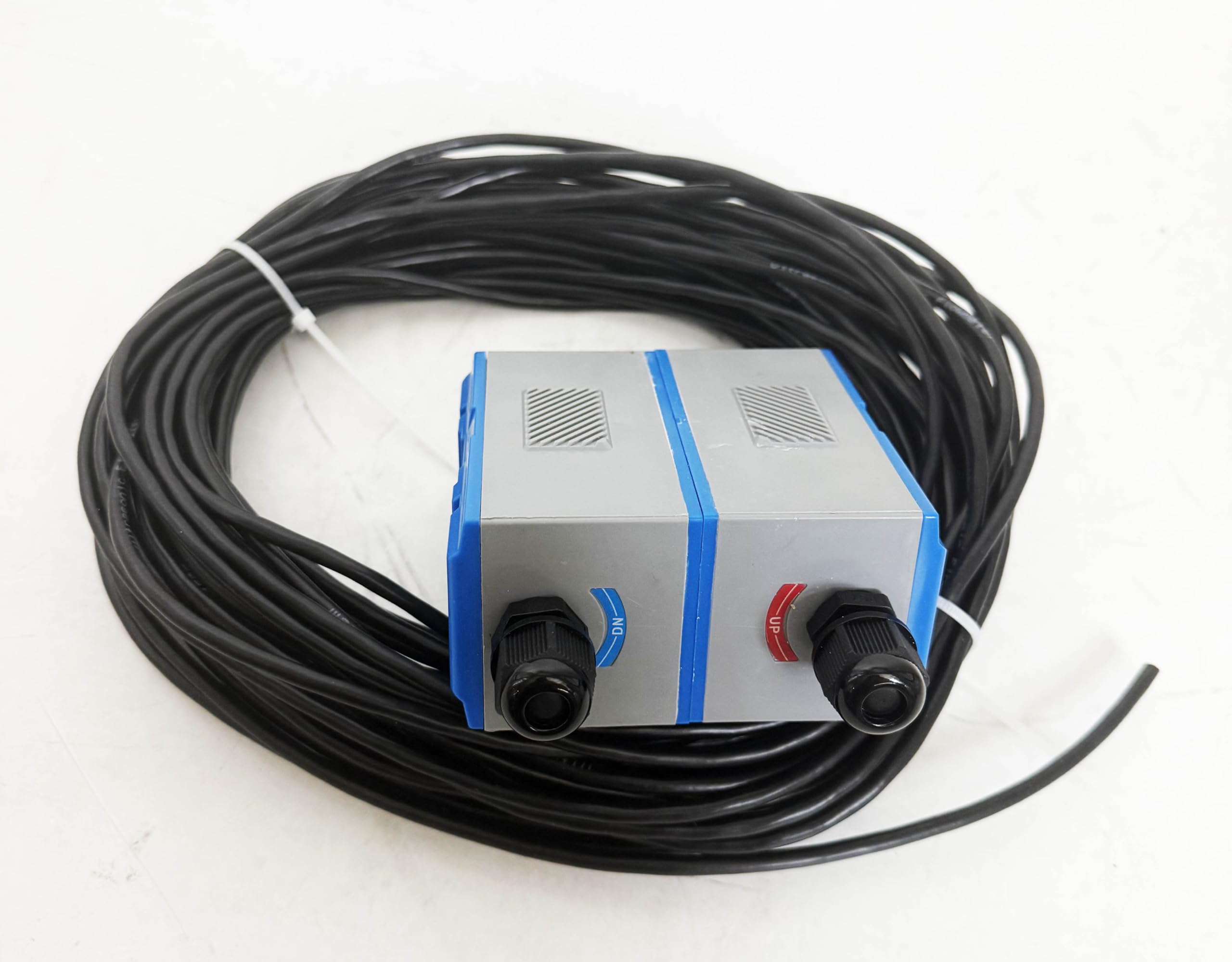
2.2 20-meter Cable
The included 20-meter twisted shielded wire cable connects the TL-1 transducers to the ultrasonic flow meter main unit. The shielding helps to minimize electromagnetic interference, ensuring reliable signal transmission.


3. Specifications
| Feature | Specification |
|---|---|
| Transducer Model | TL-1 (Large Size) |
| Compatible Pipe Diameter | DN300 ~ DN6000mm |
| Temperature Range | -30°C to 90°C (-22°F to 194°F) |
| Transducer Dimensions (L x W x H) | 69mm x 39mm x 44mm |
| Cable Type | Twisted Shielded Wire |
| Cable Length | 20 meters |
| Material | Plastic |
| Item Weight (approx.) | 1.1 pounds (total package) |
| Compatibility | TUF-2000SW, TUF-2000B, TUF-2000M, TUF-2000F Ultrasonic Flow Meters |
4. Setup and Installation
Proper installation of the TL-1 transducers is crucial for accurate flow measurement. Always refer to the specific instruction manual of your HFBTE ultrasonic flow meter main unit (e.g., TUF-2000B) for detailed connection and configuration procedures.
4.1 Connecting the Cable
- Ensure the ultrasonic flow meter main unit is powered off before making any connections.
- Connect the 20-meter twisted shielded cable to the TL-1 transducers. Ensure the connections are secure and properly sealed to prevent moisture ingress.
- Connect the other end of the cable to the designated transducer input ports on your HFBTE ultrasonic flow meter main unit. Pay attention to polarity if specified by your main unit's manual.
4.2 Transducer Placement
The TL-1 transducers are clamp-on type, meaning they attach to the exterior of the pipe. The exact spacing and orientation of the transducers on the pipe will depend on the pipe material, diameter, and the specific settings of your ultrasonic flow meter main unit. Consult your main unit's manual for precise placement instructions, including:
- Pipe Preparation: Ensure the pipe surface where the transducers will be placed is clean, smooth, and free of rust, paint, or other coatings that could interfere with ultrasonic signal transmission.
- Coupling Gel: Apply a suitable ultrasonic coupling gel between the transducer faces and the pipe surface to ensure good acoustic contact.
- Secure Attachment: Use the strong magnets on the transducers to firmly attach them to the pipe. Additional clamping mechanisms may be provided with your main unit for extra security.
- Upstream/Downstream Placement: Correctly identify and place the 'UP' (upstream) and 'DN' (downstream) transducers according to the flow direction and your main unit's requirements.
5. Operating Instructions
Once the TL-1 transducers and cable are correctly installed and connected to the HFBTE ultrasonic flow meter main unit, the operation of the system is primarily controlled via the main unit. The transducers function by sending and receiving ultrasonic signals through the fluid in the pipe, allowing the main unit to calculate flow rate.
For detailed operating procedures, including calibration, parameter settings, and data interpretation, please refer to the comprehensive user manual provided with your specific HFBTE ultrasonic flow meter main unit (e.g., TUF-2000B).
Video 5.1: HFBTE TL-1 Transducer and Cable Overview. This video provides a visual demonstration of the HFBTE TL-1 ultrasonic transducers and the 20-meter cable, showcasing their physical appearance and components.
6. Maintenance
To ensure the longevity and accurate performance of your HFBTE TL-1 transducers and cable, follow these maintenance guidelines:
- Cleanliness: Regularly clean the transducer faces and the pipe surface where they are mounted. Any dirt, grease, or residue can impair acoustic coupling and affect measurement accuracy.
- Cable Inspection: Periodically inspect the 20-meter cable for any signs of wear, cuts, or damage to the insulation. Damaged cables should be replaced to prevent signal loss or electrical hazards.
- Secure Mounting: Verify that the transducers remain securely clamped to the pipe. Vibrations or external impacts can cause displacement, leading to inaccurate readings.
- Storage: When not in use, store the transducers and cable in a clean, dry environment, away from extreme temperatures and direct sunlight.
7. Troubleshooting
If you encounter issues with your HFBTE TL-1 transducers or cable, consider the following common troubleshooting steps. For more in-depth diagnostics, refer to the troubleshooting section of your HFBTE ultrasonic flow meter main unit's manual.
7.1 No Flow Reading or Erratic Readings
- Check Connections: Ensure the 20-meter cable is securely connected to both the transducers and the main flow meter unit.
- Transducer Placement: Verify that the transducers are correctly spaced and oriented on the pipe according to the main unit's manual. Incorrect spacing is a common cause of errors.
- Coupling Gel: Confirm that sufficient ultrasonic coupling gel is applied between the transducers and the pipe surface, and that there are no air gaps.
- Pipe Condition: Ensure the pipe material and wall thickness entered into the main unit are accurate. Check for internal pipe lining or heavy corrosion that might obstruct the ultrasonic signal.
- Fluid Properties: Confirm the fluid in the pipe is suitable for ultrasonic measurement (e.g., not heavily aerated or containing excessive solids).
7.2 Cable Damage
If the 20-meter cable is visibly damaged (cuts, fraying), it may lead to signal loss or intermittent readings. Replace damaged cables with genuine HFBTE replacement parts to ensure compatibility and performance.
8. Warranty and Support
For information regarding product warranty, technical support, or replacement parts, please contact HFBTE customer service or visit the official HFBTE website. When contacting support, please have your product model (B0F3X5G34P) and any relevant purchase information available.
HFBTE Store: Visit the HFBTE Store on Amazon
