1. Introduction
The NEDLATSDY USB to SDI-12 Protocol Converter is a specialized electronic component designed to facilitate communication between a computer (via USB) and SDI-12 compatible sensors. This device enables users to capture data, debug sensor protocols, and perform tests on SDI-12 sensors with high precision and stable performance. It serves as a reliable interface for various industrial, environmental, and research applications requiring SDI-12 sensor integration.
2. Safety Information
Please read and understand all safety instructions before using this device. Failure to follow these instructions may result in electric shock, fire, or damage to the product or connected equipment.
- Power Supply: Ensure the power supply connected to the SDI-12 side (if external) matches the sensor's requirements and does not exceed the converter's specified voltage limits.
- Environmental Conditions: Operate the device in a dry environment, away from moisture, extreme temperatures, and direct sunlight.
- Handling: Handle the circuit board with care to avoid damage from electrostatic discharge. Avoid touching exposed components while the device is powered.
- Modifications: Do not attempt to modify or disassemble the device. Unauthorized modifications can void the warranty and pose safety risks.
- Ventilation: Ensure adequate ventilation around the device if it is enclosed, to prevent overheating.
3. Package Contents
Verify that all items are present in your package:
- NEDLATSDY USB to SDI-12 Protocol Converter Board
- USB Type-A to Type-B Cable (for connecting to computer)
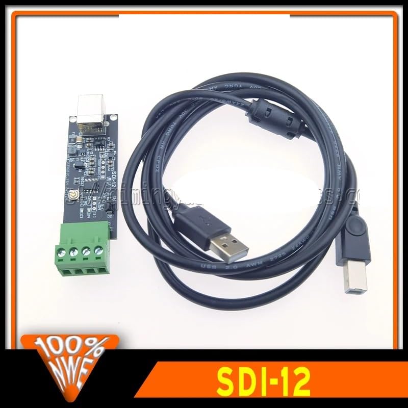
Image 3.1: The USB to SDI-12 Protocol Converter board shown alongside its accompanying USB cable.
4. Product Overview
The NEDLATSDY USB to SDI-12 Protocol Converter features a compact design with essential interfaces for seamless operation.
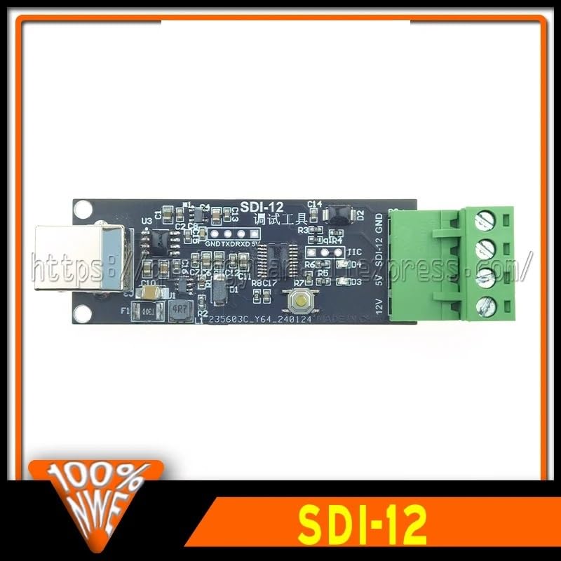
Image 4.1: Top view of the converter board, highlighting the USB port on the left and the green terminal block on the right.
4.1 Key Components
- USB Type-B Port: Located on one end of the board, this port is used to connect the converter to your computer for power and data communication.
- SDI-12 Terminal Block: A green screw terminal block provides connections for the SDI-12 sensor. Typically, these include Data, Ground (GND), and Power (5V or 12V, depending on the specific model and configuration).
- Indicator LEDs: (If present, not clearly visible in images but common for such devices) Small LEDs may indicate power status, data transmission (TX), and data reception (RX).
- Integrated Circuitry: The board contains various integrated circuits and passive components responsible for USB-to-serial conversion and SDI-12 protocol handling.
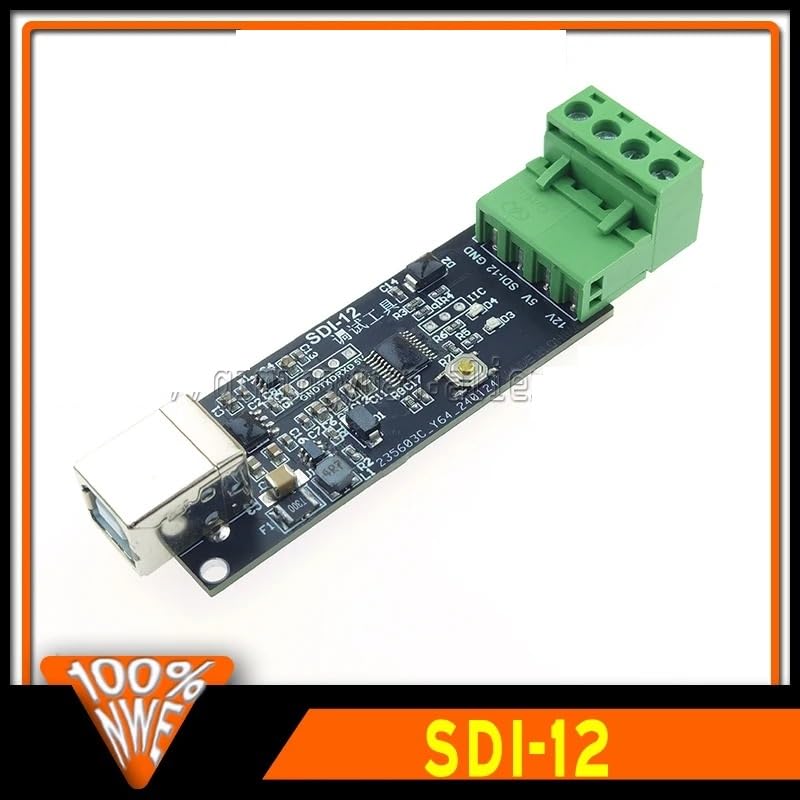
Image 4.2: Angled view of the converter board, providing a clearer perspective of the USB connector and the SDI-12 terminal block.
5. Setup
Follow these steps to set up your USB to SDI-12 Protocol Converter:
- Driver Installation:
Connect the USB to SDI-12 converter to your computer using the provided USB cable. For most modern operating systems (Windows 10/11, macOS, Linux), the necessary USB serial drivers will install automatically. If not, you may need to manually install drivers for the USB-to-serial chip (e.g., FTDI, CH340, CP210x) used on the board. Refer to the manufacturer's website for specific driver downloads if automatic installation fails.
- Identify COM Port:
After successful driver installation, the converter will appear as a virtual COM port in your computer's Device Manager (Windows) or equivalent system information utility (macOS/Linux). Note the assigned COM port number (e.g., COM3, /dev/ttyUSB0).
- Connect SDI-12 Sensor:
Connect your SDI-12 sensor to the green terminal block on the converter board. Ensure correct polarity and pin assignments:
- Data: Connect the SDI-12 data line from your sensor to the Data terminal.
- GND: Connect the ground line from your sensor to the GND terminal.
- Power (5V/12V): Connect the power supply for your sensor to the appropriate power terminal (5V or 12V), if the converter provides power or if an external power source is used. Consult your sensor's manual for its power requirements.
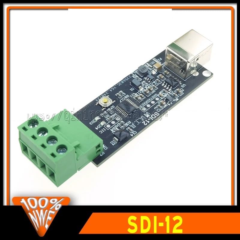
Image 5.1: Detailed view of the green terminal block, showing connection points for SDI-12 data, ground, and power.
6. Operating Instructions
Once the converter is connected and drivers are installed, you can begin communicating with your SDI-12 sensors.
- Software Selection:
Use a serial terminal program (e.g., PuTTY, Tera Term, CoolTerm) or specialized SDI-12 software to communicate with the converter via the identified COM port. Configure the serial port settings (baud rate, data bits, parity, stop bits) as required by the SDI-12 protocol (typically 1200 baud, 8 data bits, even parity, 1 stop bit).
- Sending SDI-12 Commands:
SDI-12 communication involves sending specific commands to the sensor and receiving responses. Commands typically start with the sensor address (e.g., '0' for address 0) followed by the command character and a checksum. For example, to request sensor identification from address '0', you might send "0I!".
- Receiving Data:
The converter will translate the SDI-12 sensor's response into serial data, which will be displayed in your terminal program. Interpret this data according to the SDI-12 protocol and your sensor's documentation.
- Debugging:
The converter acts as a transparent bridge, allowing you to observe the raw SDI-12 communication. This is invaluable for debugging sensor issues, verifying command syntax, and understanding sensor behavior.

Image 6.1: A detailed view of the integrated circuits and components on the converter board, which manage the USB and SDI-12 communication protocols.
7. Maintenance
Proper care and maintenance will ensure the longevity and reliable performance of your converter.
- Cleaning: Disconnect the device from all power sources before cleaning. Use a soft, dry, lint-free cloth to wipe the surface. Do not use liquid cleaners or solvents.
- Storage: Store the converter in a cool, dry place, away from direct sunlight and extreme temperatures, when not in use.
- Inspection: Periodically inspect the USB port and terminal block for any signs of damage or corrosion. Ensure all connections are secure.
8. Troubleshooting
If you encounter issues with your USB to SDI-12 Protocol Converter, refer to the following common problems and solutions:
- Device Not Recognized by Computer:
- Ensure the USB cable is securely connected to both the converter and the computer.
- Try a different USB port on your computer.
- Verify that the necessary USB serial drivers are installed. Check Device Manager for unrecognized devices and install drivers manually if needed.
- Test with a different USB cable.
- No Communication with SDI-12 Sensor:
- Check the wiring between the converter and the SDI-12 sensor. Ensure Data, GND, and Power connections are correct and secure.
- Verify the sensor is powered correctly and functioning independently.
- Confirm the serial port settings (baud rate, parity, etc.) in your terminal software match the SDI-12 protocol requirements.
- Ensure the SDI-12 command syntax is correct, including the sensor address and checksum.
- Try a different SDI-12 sensor if available, to rule out sensor-specific issues.
- Intermittent Connection/Data Loss:
- Check for loose connections on both the USB and SDI-12 sides.
- Ensure there is no electromagnetic interference from other devices.
- Verify the power supply to the SDI-12 sensor is stable.
9. Specifications
| Feature | Specification |
|---|---|
| Model | USB-SDI12-CONV |
| Brand | NEDLATSDY |
| Input Interface | USB Type-B |
| Output Interface | SDI-12 (Screw Terminal Block) |
| SDI-12 Baud Rate | 1200 bps (standard) |
| Operating Voltage (USB) | 5V DC (via USB) |
| SDI-12 Power Output | 5V or 12V (depending on board configuration and external power) |
| Operating Temperature | -20°C to +70°C (typical, inferred) |
| Dimensions | Compact PCB design (specific dimensions not provided, inferred) |
| ASIN | B0F3WXWPYZ |
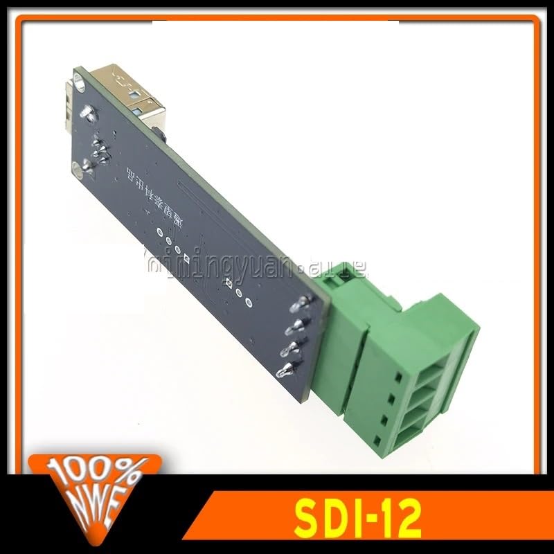
Image 9.1: Bottom view of the converter board, illustrating the compact layout and solder points.
10. Warranty and Support
NEDLATSDY is committed to providing high-quality electronic components and excellent customer service.
- Money-Back Guarantee: We offer a money-back guarantee, reflecting our confidence in the quality and performance of our products. Please refer to your purchase terms for specific details regarding returns and refunds.
- Customer Support: For any questions, technical assistance, or concerns regarding your USB to SDI-12 Protocol Converter, please contact our customer support team. Our knowledgeable team is available to provide support and ensure your satisfaction.
- Contact Information: Please refer to your purchase documentation or the seller's information on the platform where you purchased the product for specific contact details.