1. Introduction
This manual provides essential information for the safe and efficient operation, installation, and maintenance of the YMZYEKB FX3U-14MT Programmable Logic Controller (PLC). The FX3U-14MT is an industrial control board designed for various automation tasks, featuring digital inputs/outputs, analog inputs/outputs, and serial communication capabilities.
Please read this manual thoroughly before attempting to install or operate the device. Keep this manual for future reference.
2. Safety Information
Observe the following safety precautions to prevent personal injury and damage to the equipment:
- Electrical Safety: Ensure power is disconnected before wiring or performing maintenance. Only qualified personnel should perform electrical connections.
- Proper Grounding: Always ensure the PLC and associated equipment are properly grounded to prevent electrical shock and ensure stable operation.
- Environmental Conditions: Operate the PLC within specified environmental conditions (temperature, humidity, vibration) to prevent malfunction.
- Correct Wiring: Verify all wiring connections are correct and secure before applying power. Incorrect wiring can cause damage to the PLC or connected devices.
- Emergency Stop: Implement appropriate emergency stop mechanisms in your system design.
3. Product Overview
The YMZYEKB FX3U-14MT is a compact and powerful programmable logic controller. It integrates various functionalities essential for industrial automation.
Key Features:
- Digital I/O: 14 Digital Inputs (DI) and 10 Digital Outputs (DO).
- Analog I/O: 6 Analog Inputs (AI) and 2 Analog Outputs (AO).
- Communication: RS232 and RS485 serial communication ports for connectivity with other devices or HMI.
- High-Speed Counting: Supports high-speed pulse inputs for precise control.
- Pulse Output: Capable of pulse outputs for stepper or servo motor control.
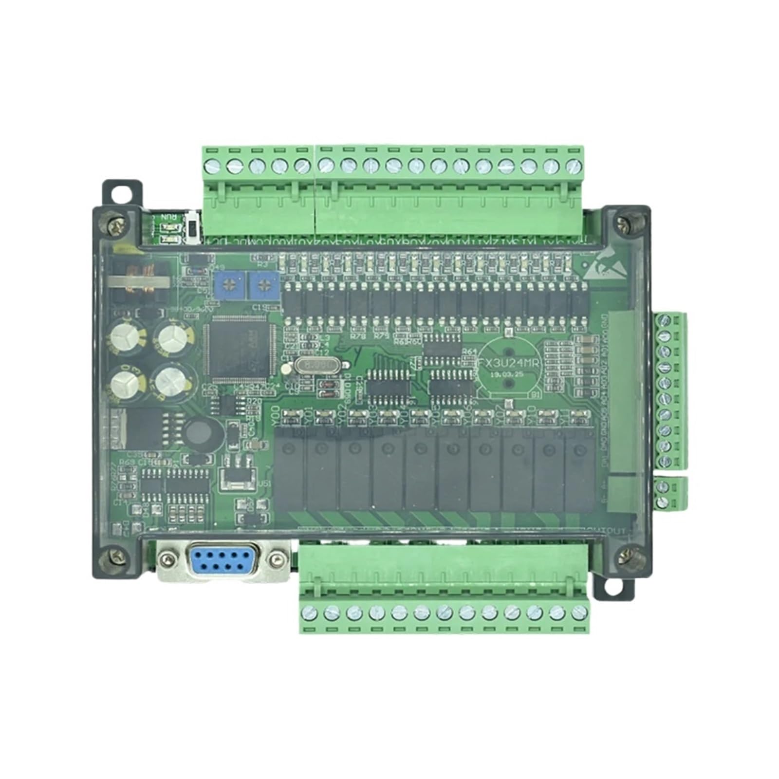
Figure 3.1: Top-down view of the YMZYEKB FX3U-14MT Programmable Logic Controller, showing the main circuit board, green terminal blocks for inputs and outputs, and a transparent protective casing.
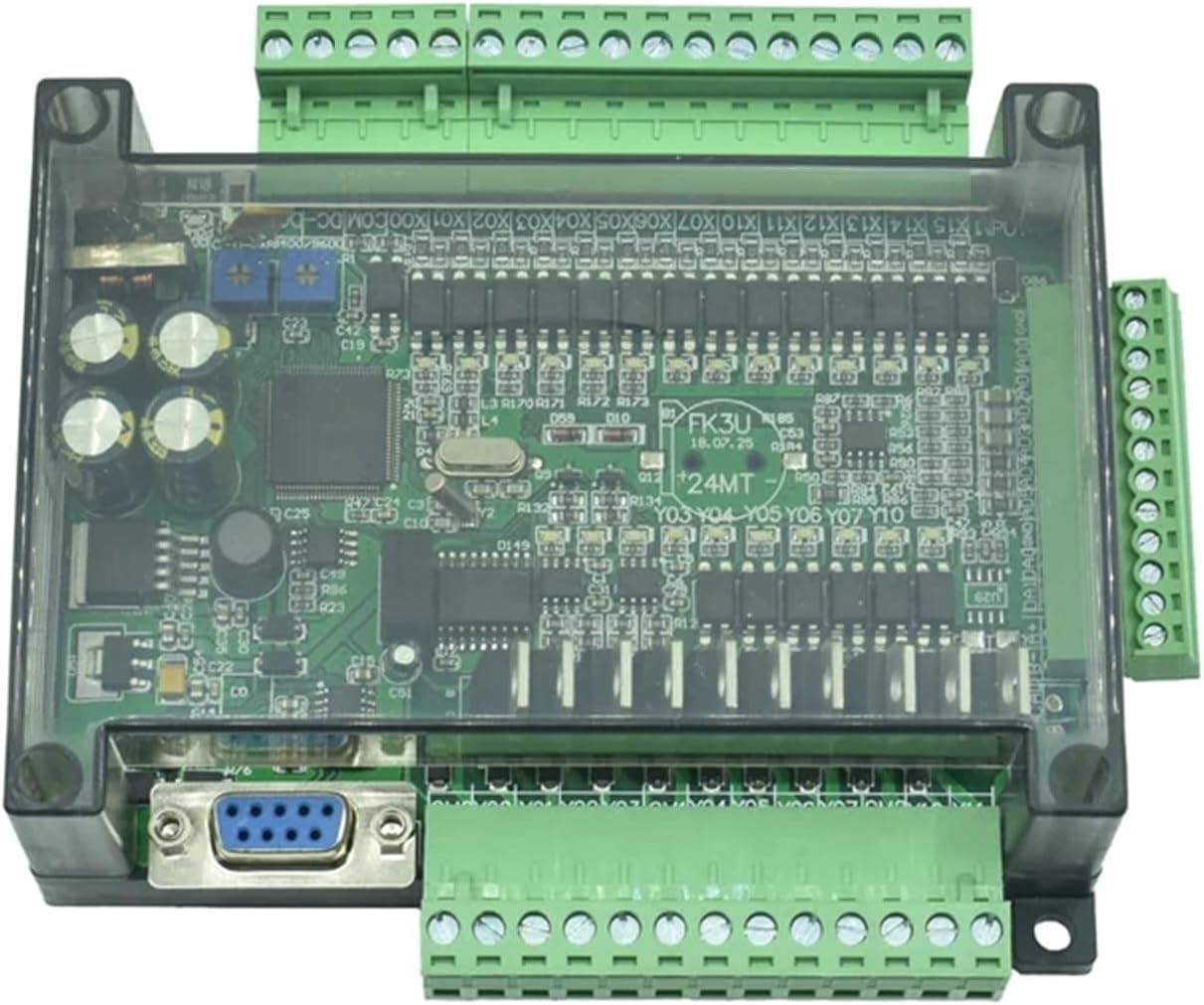
Figure 3.2: Angled view of the YMZYEKB FX3U-14MT PLC, providing a clearer perspective of the various green terminal blocks for wiring connections and the RS232 port.
4. Specifications
| Feature | Specification |
|---|---|
| Model | FX3U-14MT |
| Digital Inputs (DI) | 14 |
| Digital Outputs (DO) | 10 |
| Analog Inputs (AI) | 6 |
| Analog Outputs (AO) | 2 |
| Communication Ports | RS232, RS485 |
| Package Dimensions | 1.18 x 0.79 x 0.39 inches |
| Item Weight | 1.76 ounces |
| Manufacturer | YMZYEKB |
5. Setup and Installation
5.1 Mounting
The FX3U-14MT PLC is designed for panel mounting. Secure the unit using appropriate screws through the mounting holes provided on the casing. Ensure adequate ventilation around the unit to prevent overheating.
5.2 Power Supply Connection
Connect a stable DC power supply (typically 24V DC) to the designated power terminals. Observe correct polarity. Refer to the wiring diagram for specific terminal assignments.
5.3 Wiring Digital Inputs and Outputs
Connect your sensors, switches, and other input devices to the digital input terminals (DI). Connect actuators, relays, and other output devices to the digital output terminals (DO). Ensure all connections are firm and insulated.
5.4 Wiring Analog Inputs and Outputs
Connect analog sensors (e.g., temperature, pressure transducers) to the analog input terminals (AI). Connect analog actuators (e.g., variable frequency drives, proportional valves) to the analog output terminals (AO). Pay close attention to signal types (voltage/current) and ranges.
5.5 Communication Port Setup (RS232/RS485)
Use the RS232 port for direct connection to a programming device (PC) or HMI. The RS485 port allows for multi-drop communication with other devices in a network. Configure communication parameters (baud rate, data bits, stop bits, parity) in your programming software to match the connected devices.
6. Operating Instructions
6.1 Programming Software
The FX3U-14MT PLC is typically programmed using compatible PLC programming software, such as GX Works2 or GX Developer. Install the software on your PC and ensure the correct drivers are installed for the communication port.
6.2 Creating a Program
Develop your control logic using ladder diagram, instruction list, or other supported programming languages within the software. Define input/output assignments, timers, counters, and other control elements.
6.3 Downloading and Running the Program
- Connect your PC to the PLC via the RS232 port.
- In the programming software, establish communication with the PLC.
- Download the compiled program to the PLC's memory.
- Switch the PLC to RUN mode (either via software command or a physical switch if available).
6.4 Monitoring and Debugging
Use the monitoring features of the programming software to observe the status of inputs, outputs, internal relays, and data registers in real-time. This is crucial for debugging and verifying program execution.
7. Maintenance
7.1 Cleaning
Periodically clean the exterior of the PLC with a soft, dry cloth. Avoid using solvents or abrasive cleaners. Ensure ventilation openings are free from dust and debris.
7.2 Environmental Checks
Regularly inspect the operating environment to ensure it remains within the specified temperature and humidity ranges. Excessive heat or moisture can shorten the lifespan of the device.
7.3 Connection Verification
Periodically check all wiring connections for tightness and signs of corrosion or damage. Loose connections can lead to intermittent operation or system failures.
8. Troubleshooting
8.1 Power Indicator Not On
- Check Power Supply: Verify that the 24V DC power supply is connected correctly and is providing the specified voltage.
- Check Wiring: Ensure power supply wires are securely connected to the PLC terminals and polarity is correct.
8.2 Communication Failure
- Cable Connection: Ensure the RS232 or RS485 cable is securely connected to both the PLC and the programming device.
- Communication Parameters: Verify that the baud rate, data bits, stop bits, and parity settings in the software match those configured on the PLC.
- Driver Installation: Confirm that the correct USB-to-serial converter drivers (if used) are installed on your PC.
8.3 Digital Input Not Responding
- Sensor Check: Test the input sensor or switch independently to ensure it is functioning correctly.
- Wiring: Check the wiring from the sensor to the PLC input terminal for breaks or loose connections.
- Program Logic: Verify that the PLC program logic is correctly reading and processing the input.
8.4 Digital Output Not Activating
- Actuator Check: Test the output device (e.g., relay, solenoid) independently.
- Wiring: Check the wiring from the PLC output terminal to the actuator.
- Program Logic: Ensure the PLC program logic is correctly commanding the output to activate.
- Output Type: Confirm the output type (e.g., relay, transistor) is suitable for the connected load.
9. Warranty and Support
For warranty information, please refer to the terms and conditions provided by your seller or contact YMZYEKB directly. Technical support may be available through the point of purchase or the manufacturer's official channels.
When contacting support, please have your product model (FX3U-14MT) and purchase details readily available.