1. Introduction
Thank you for choosing the YedaHcy 200EP Wire Tracer Kit. This kit is designed for efficient and accurate maintenance of cables and wires. It is an essential tool for professionals working with telephone, data, internet, voice, security, and communication cables. The kit includes an inductive amplifier (detector) and a wire tracker (toner) to perform various functions such as line tracing, short circuit testing, and cable identification.
2. Important Safety Information
- WARNING: Do not test any cable while it is powered. Always ensure the circuit is de-energized before connecting the wire tracer kit.
- Always wear appropriate personal protective equipment (PPE) when working with electrical systems.
- Do not use the device in wet conditions or in environments with explosive gases or vapors.
- Keep the device away from children.
- Use only the specified battery type (9V 6F22) and ensure correct polarity during installation.
3. Package Contents
Please verify that all items listed below are present in your package:
- 1 x Inductive Amplifier (Detector)
- 1 x Wire Tracker (Toner)
- 1 x Test Head (Probe Tip)
- 1 x User Manual (This document)
- 1 x Storage Bag
Note: A 9V 6F22 battery is required for operation and is not included in the package.

Figure 3.1: The YedaHcy 200EP Wire Tracer Kit, showing the inductive amplifier, wire tracker (toner), connecting cables, test head, and storage bag.
4. Product Overview
The YedaHcy 200EP Wire Tracer Kit consists of two main units: the Inductive Amplifier (Receiver) and the Wire Tracker (Transmitter/Toner).
4.1 Inductive Amplifier (Detector)
This handheld unit is used to detect the tone generated by the Wire Tracker. It features an adjustable induction amplifier for varying sensitivity and an integrated speaker for audible indication. The probe tip allows for precise tracing of wires.

Figure 4.1: Close-up view of the inductive amplifier's probe tip, used for precise wire tracing.
4.2 Wire Tracker (Toner)
The Wire Tracker is the transmitter unit that generates a tone signal onto the cable being tested. It includes connections for various cable types and indicators for tone, continuity, and polarity.
5. Setup
5.1 Battery Installation (Inductive Amplifier)
- Locate the battery compartment on the back of the Inductive Amplifier unit.
- Carefully open the battery compartment cover.
- Insert one 9V 6F22 battery, ensuring correct polarity (+/-) as indicated inside the compartment.
- Close the battery compartment cover securely. Do not overtighten the screw.

Figure 5.1: Rear view of the inductive amplifier, highlighting the battery compartment location.

Figure 5.2: Detailed view of the battery compartment on the inductive amplifier, showing where to insert the 9V battery.
6. Operating Instructions
Always ensure the cable or circuit you are testing is de-energized before connecting the Wire Tracker.
6.1 Line Tracing
- Connect the Wire Tracker (toner) to the cable you wish to trace. Use the appropriate connector (e.g., RJ11, RJ45, alligator clips) for your cable type.
- Turn on the Wire Tracker and select the 'TONE' function. This will send an audible signal through the cable.
- Turn on the Inductive Amplifier (detector).
- Adjust the sensitivity (gain) of the Inductive Amplifier as needed. Higher sensitivity allows detection from further away, while lower sensitivity helps pinpoint the exact wire.
- Move the probe tip of the Inductive Amplifier along the path of the suspected cable. The amplifier will emit an audible tone, which will be loudest when directly over the energized wire.
- Follow the tone to trace the cable's path and identify its termination point.
6.2 Short Circuit Testing
- Ensure the cable is completely disconnected from any power source and equipment.
- Connect the Wire Tracker to the cable.
- Select the 'CONTINUITY' or 'SHORT' function on the Wire Tracker (if available). The unit will indicate if a short circuit is detected.
- Alternatively, use the Inductive Amplifier to trace for a sudden drop or change in tone, which can indicate a short.
6.3 Continuity and Polarity Testing
The Wire Tracker unit often includes indicators for continuity and polarity. Refer to the markings on the unit for specific usage:
- Continuity: Connect the Wire Tracker to the ends of a cable. An indicator light or tone will confirm if there is a continuous path.
- Polarity: When connected to a live telephone line, the polarity indicator will show the correct line polarity.
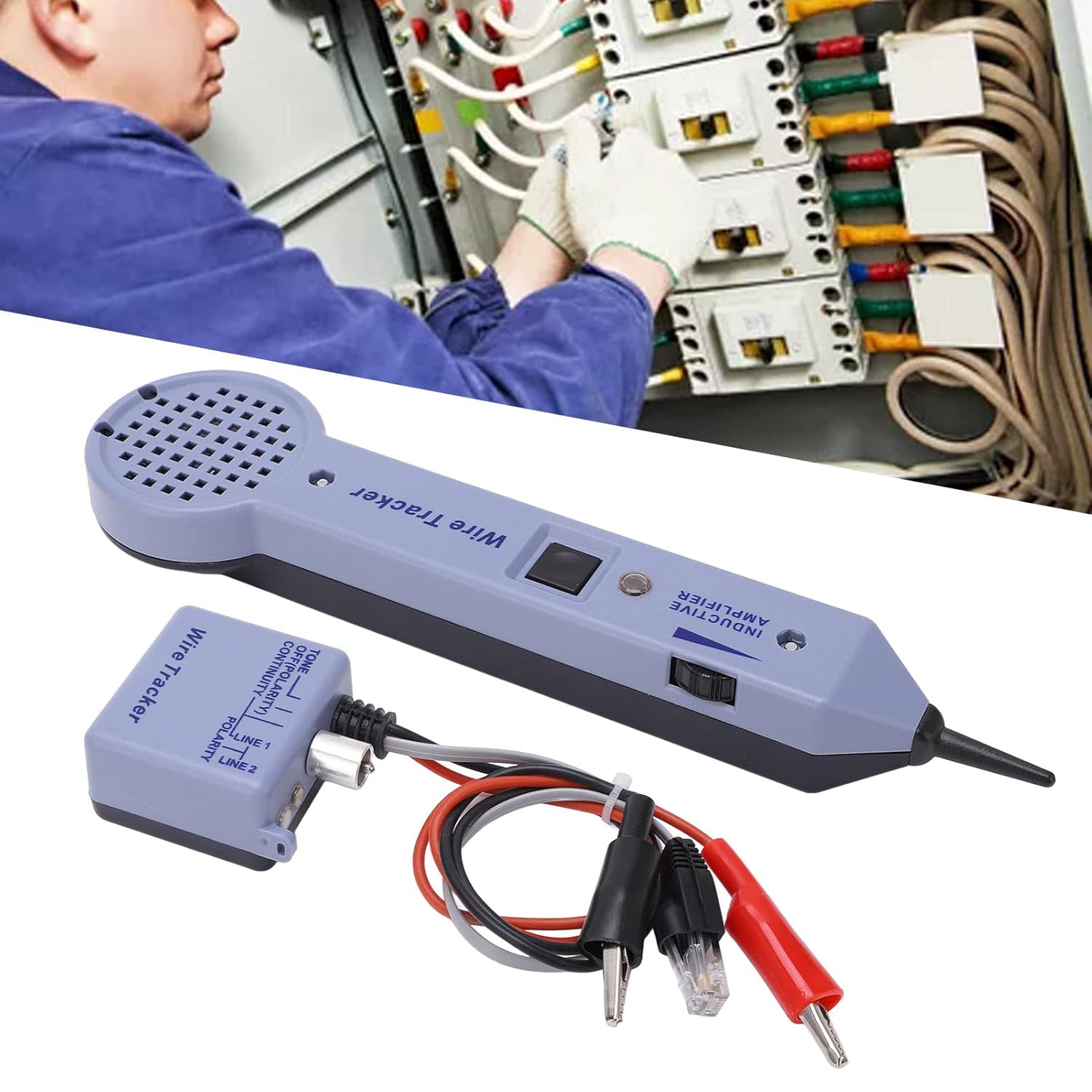
Figure 6.1: Illustrative image of the wire tracer kit in use, demonstrating cable tracing within an electrical setup.
7. Maintenance
7.1 Cleaning
Wipe the device with a soft, dry cloth. Do not use abrasive cleaners or solvents, as they may damage the ABS material.
7.2 Battery Replacement
When the device's performance degrades or the indicators become dim, it is time to replace the 9V battery in the Inductive Amplifier. Follow the battery installation steps outlined in Section 5.1.
7.3 Storage
Store the kit in its provided storage bag in a cool, dry place away from direct sunlight and extreme temperatures. Remove the battery if the device will not be used for an extended period to prevent leakage.
8. Troubleshooting
| Problem | Possible Cause | Solution |
|---|---|---|
| No tone from Inductive Amplifier | Dead or incorrectly installed battery in Amplifier Toner not turned on or not connected Cable is powered (safety feature) | Replace battery, check polarity Ensure toner is on and connected correctly De-energize the cable before testing |
| Weak or inconsistent tone | Low battery in Amplifier Amplifier sensitivity too low Cable is shielded or deeply buried | Replace battery Increase amplifier gain/sensitivity Move probe closer to the cable, try different angles |
| Toner indicators not working | Poor connection to cable Faulty cable | Check all connections Inspect cable for damage |
9. Specifications
- Item Type: Wire Tracer Kit
- Model: 200EP
- Material: ABS
- Battery: 9V 6F22 battery x 1 (not included)
- Application: Line tracing, short circuit testing, clear/busy/recognition for various cables.
- Gain: 30 dB
- Input Impedance: 100MOhm
- Probe Tip (Minimum):
- Metal Tip: 0 Ohm
- Plastic Head: 300 Ohm
- Package Dimensions: 10.24 x 4.72 x 2.76 inches
- Item Weight: 10.37 ounces
10. Warranty and Support
For warranty information or technical support, please refer to the contact details provided with your purchase or visit the official YedaHcy website. Keep your purchase receipt as proof of purchase.