1. Introduction
This user manual provides comprehensive instructions for the assembly, operation, and maintenance of your NEISEMOVI RDA5807FP FM Radio DIY Kit. This kit is designed for enthusiasts and learners to build a functional FM radio receiver operating in the 65-108MHz frequency range, featuring an RDA5807FP FM receiver chip and a TDA2822 power amplifier module for clear audio output. Please read this manual carefully before beginning assembly to ensure proper functionality and a rewarding building experience.
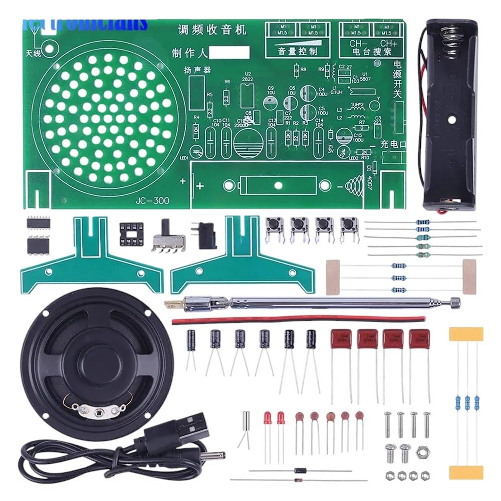
Figure 1: All components of the RDA5807FP FM Radio DIY Kit, including the PCB, speaker, battery holder, antenna, and various electronic parts.
2. Product Overview
The RDA5807FP FM Radio DIY Kit offers an educational and practical experience in electronics assembly. Key features include:
- Wide Frequency Range: Receives FM broadcasts from 65MHz to 108MHz.
- Integrated Amplifier: Utilizes the TDA2822 power amplifier module for enhanced audio output.
- Auto Searching Function: Simplifies station tuning.
- High-Quality Components: Constructed with reliable electronic components for stable performance.
- Educational Value: Ideal for learning basic electronics and soldering skills.

Figure 2: A variety of electronic components typically found in DIY kits, illustrating the types of parts used in this radio kit.
3. Components List
Before starting assembly, verify that all components listed below are present in your kit. Refer to Figure 1 for a visual representation of the main components.
- Printed Circuit Board (PCB) with component markings
- RDA5807FP FM Receiver Module (IC)
- TDA2822 Power Amplifier IC
- Speaker
- Battery Holder (for AA batteries)
- Telescopic Antenna
- Various Resistors (e.g., 10kΩ, 1kΩ, 220Ω)
- Various Capacitors (e.g., electrolytic, ceramic)
- Diodes (e.g., 1N4148)
- LEDs (Power indicator, tuning indicator)
- Push Buttons (for tuning, auto-search)
- Potentiometer (for volume control)
- Power Switch
- DC Power Jack
- Connecting Wires
- Fasteners (screws, nuts)

Figure 3: An illustrative diagram showing common semiconductor and passive electronic components, similar to those included in the kit.
4. Setup and Assembly Instructions
Assembly of this kit requires basic soldering skills and tools (soldering iron, solder, wire cutters, multimeter). Always work in a well-ventilated area and take appropriate safety precautions.
4.1. Safety Precautions
- Ensure your soldering iron is properly grounded and at a safe temperature.
- Wear safety glasses to protect your eyes from solder splatter.
- Avoid inhaling solder fumes; use a fume extractor or work in a well-ventilated space.
- Double-check component polarity (diodes, LEDs, electrolytic capacitors, ICs) before soldering.
- Do not apply power until all components are correctly soldered and inspected.
4.2. Assembly Steps
- Prepare the PCB: Familiarize yourself with the component placement markings on the Printed Circuit Board.
- Solder Resistors and Diodes: Start with the smallest components. Insert resistors and diodes according to their values and polarity (for diodes) and solder them in place. Trim excess leads.
- Solder Capacitors: Install ceramic capacitors (non-polarized) and then electrolytic capacitors, ensuring correct polarity for the latter (long lead is positive, marked side is negative).
- Solder IC Sockets (if provided) or ICs: If sockets are included, solder them first. If soldering ICs directly, align the notch or dot on the IC with the corresponding mark on the PCB.
- Solder Buttons, Switches, and Potentiometer: Install the push buttons, power switch, and volume potentiometer.
- Connect Speaker: Solder the speaker wires to the designated pads on the PCB.
- Install Battery Holder and Antenna: Secure the battery holder and solder its wires to the power input pads. Attach the telescopic antenna to its designated connection point.
- Final Inspection: Carefully inspect all solder joints for bridges, cold joints, or unsoldered pins. Verify component placement and polarity.
5. Operating Instructions
5.1. Powering On
- Insert Batteries: Open the battery compartment of the battery holder and insert the required AA batteries, observing correct polarity. Alternatively, connect a compatible DC power adapter to the DC power jack.
- Extend Antenna: Fully extend the telescopic antenna for optimal signal reception.
- Turn On: Flip the power switch to the "ON" position. The power indicator LED should illuminate.
5.2. Tuning and Volume Control
- Adjust Volume: Rotate the potentiometer knob to adjust the desired audio volume.
- Manual Tuning: Use the "CH-" and "CH+" buttons to manually scan through frequencies. A tuning indicator LED may light up when a strong signal is received.
- Auto Search: Press the "Auto Search" button (often labeled "SCAN" or similar) to automatically scan and stop at available FM stations.
For best reception, try repositioning the antenna or the radio itself.
6. Maintenance
- Cleaning: Use a soft, dry cloth to clean the exterior of the radio. Avoid using liquid cleaners or solvents, which can damage components.
- Storage: When not in use for extended periods, remove the batteries to prevent leakage and store the radio in a cool, dry place away from direct sunlight and extreme temperatures.
- Component Check: Periodically inspect solder joints and connections for any signs of wear or damage.
7. Troubleshooting
If you encounter issues with your FM radio kit, refer to the following common problems and solutions:
| Problem | Possible Cause | Solution |
|---|---|---|
| No power/LED not lighting up |
|
|
| No sound from speaker |
|
|
| Poor reception/Static |
|
|
| Buttons not responding |
|
|
8. Technical Specifications
- Model: RDA5807FP FM Radio DIY Kit
- FM Frequency Range: 65MHz - 108MHz
- Receiver Chip: RDA5807FP
- Audio Amplifier: TDA2822
- Power Supply: DC 3V (2x AA batteries) or external DC power adapter (not included)
- Audio Output: Integrated Speaker
- Features: Auto Searching, Manual Tuning, Volume Control
9. Warranty and Customer Support
NEISEMOVI is committed to providing high-quality products and excellent customer service. This product comes with a Money-Back Guarantee, reflecting our confidence in its quality and performance.
If you have any questions, concerns, or require assistance with your RDA5807FP FM Radio DIY Kit, please do not hesitate to contact our customer support team. We are ready to assist you to ensure the best possible experience.
For support, please refer to the contact information provided with your purchase or visit the NEISEMOVI official website.

