1. Introduction
This instruction manual provides comprehensive guidance for the L6AS0F7 CSR8675 Bluetooth 5.0 Audio Module. This module is designed for integration into various audio and video equipment, offering high-quality wireless audio transmission with support for LDAC and I2S interfaces. Please read this manual carefully before installation and operation to ensure proper functionality and safety.
2. Product Overview
The L6AS0F7 CSR8675 Bluetooth 5.0 Audio Module is a compact development kit featuring the CSR8675 chipset. It supports Bluetooth 5.0 for stable and efficient wireless connectivity, including advanced audio codecs like LDAC for high-resolution audio. The module provides I2S and SPDIF output options, making it versatile for various audio applications such as headphones, speakers, amplifiers, and digital-to-analog converters (DACs).

Figure 2.1: Top view of the L6AS0F7 CSR8675 Bluetooth 5.0 Audio Module.
3. Component Identification
Familiarize yourself with the key components of the module as shown in the diagram below:

Figure 3.1: Labeled components of the module. Key components include the SMA antenna connector, the CSR8675 main chip, and the LED indicator.
- SMA Connector: Used for connecting an external antenna to ensure optimal Bluetooth signal reception.
- CSR8675 Chip: The core Bluetooth audio processing unit.
- LED: Status indicator light.
4. Pinout Diagram
The module features a set of pins for power, audio output, and control. Refer to the pinout diagram for correct connections:
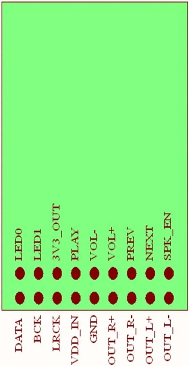
Figure 4.1: Pinout configuration of the L6AS0F7 CSR8675 module.
| Pin Name | Description |
|---|---|
| DATA | I2S Data Output |
| BCK | I2S Bit Clock Output |
| LRCK | I2S Left/Right Clock Output |
| VDD_IN | Power Input (e.g., 3.3V) |
| GND | Ground |
| OUT_R+ | Right Channel Audio Output (Positive) |
| OUT_R- | Right Channel Audio Output (Negative) |
| OUT_L+ | Left Channel Audio Output (Positive) |
| OUT_L- | Left Channel Audio Output (Negative) |
| LED0 | LED Output 0 |
| LED1 | LED Output 1 |
| 3V3_OUT | 3.3V Power Output |
| PLAY | Play/Pause Control Input |
| VOL- | Volume Down Control Input |
| VOL+ | Volume Up Control Input |
| PREV | Previous Track Control Input |
| NEXT | Next Track Control Input |
| SPK_EN | Speaker Enable Output |
5. Example Wiring Diagram
The following diagram illustrates a typical wiring setup for connecting control buttons and LEDs to the module. This example shows how to interface external components for basic playback control and status indication.

Figure 5.1: Example wiring for control buttons and LEDs.
Key points from the wiring diagram:
- Control inputs (PLAY, VOL-, VOL+, PREV, NEXT) are typically connected to momentary push buttons, often with pull-up resistors (e.g., 1KΩ) to VDD_IN or a suitable voltage source, and the button connecting the pin to ground when pressed.
- LED outputs (LED0, LED1) are connected to LEDs in series with current-limiting resistors (e.g., 1KΩ) to ground.
- Ensure proper power supply (VDD_IN and GND) is connected to the module.
6. Setup Instructions
- Power Connection: Connect a stable power supply (e.g., 3.3V) to the VDD_IN pin and connect the ground of your power supply to the GND pin. Ensure the voltage is within the module's specified operating range.
- Antenna Connection: Attach a suitable 2.4GHz antenna to the SMA Connector for optimal Bluetooth performance.
- Audio Output: Connect the I2S pins (DATA, BCK, LRCK) to your Digital-to-Analog Converter (DAC) or other I2S-compatible audio processing unit. Alternatively, use the differential analog outputs (OUT_R+, OUT_R-, OUT_L+, OUT_L-) for direct connection to an amplifier or headphone driver.
- Control Inputs (Optional): If using external buttons for control (Play/Pause, Volume, Track Skip), connect them to the respective pins (PLAY, VOL-, VOL+, PREV, NEXT) as per the example wiring diagram (Figure 5.1).
- LED Indicators (Optional): Connect LEDs to the LED0 and LED1 pins with appropriate current-limiting resistors to visualize module status.
7. Operating Instructions
- Power On: Apply power to the module. The LED indicator(s) should illuminate or blink, indicating the module is active and in pairing mode.
- Bluetooth Pairing: On your source device (e.g., smartphone, tablet, computer), enable Bluetooth and search for available devices. The module should appear with a name similar to 'CSR8675 Audio' or 'L6AS0F7 Audio'. Select it to pair.
- Audio Playback: Once paired, play audio from your source device. The audio will be transmitted wirelessly to the module and output via the configured I2S or analog outputs.
- Control Functions: Use the connected control buttons (if implemented) to manage playback (Play/Pause), adjust volume (Volume Up/Down), and skip tracks (Previous/Next).
- Power Off: Disconnect the power supply to turn off the module.
8. Specifications
| Feature | Detail |
|---|---|
| Model Number | L6AS0F7 (TDJLCSR8765) |
| Bluetooth Version | 5.0 |
| Chipset | CSR8675 |
| Audio Codec Support | LDAC, I2S, SPDIF (capabilities based on CSR8675) |
| Output Interfaces | I2S, Differential Analog Audio |
| Compatible Equipment | Earphones, Headphones, Speakers, Amplifiers, Players, Digital-to-Analog Converters (DAC), Professional Audio Equipment, Stage Equipment, Recording Equipment |
| Package Dimensions | 1.18 x 0.79 x 0.39 inches (approx.) |
| Item Weight | 1.76 ounces (approx.) |
| Assembly Required | No (module itself), external assembly required for integration |
| Number of Pieces | 1 (module) |
9. Troubleshooting
- No Power:
- Ensure the power supply is correctly connected to VDD_IN and GND, and that the voltage is within the specified range.
- Check for loose connections or damaged wires.
- Cannot Pair:
- Make sure the module is powered on and the LED indicator is active (e.g., blinking).
- Ensure no other device is currently paired with the module. Disconnect from any previously paired devices.
- Move the source device closer to the module to rule out range issues.
- Verify the antenna is securely connected to the SMA port.
- No Audio Output:
- Confirm the module is successfully paired with the source device.
- Check the volume levels on both the source device and any connected amplifier/DAC.
- Verify that the I2S or analog audio outputs are correctly wired to your audio system.
- Ensure the connected DAC or amplifier is powered on and functioning correctly.
- Poor Audio Quality/Interference:
- Ensure the external antenna is properly installed.
- Reduce the distance between the module and the source device.
- Minimize interference from other 2.4GHz wireless devices (Wi-Fi routers, other Bluetooth devices).
- Check power supply for noise; consider adding filtering if necessary.
10. Maintenance
- Keep the module in a dry environment, away from moisture and extreme temperatures.
- Avoid exposing the module to static electricity. Handle with care, preferably using anti-static precautions.
- Do not attempt to disassemble or modify the module, as this may void any potential warranty and could damage the device.
- Clean the module gently with a dry, soft cloth if necessary. Avoid using liquids or harsh chemicals.
11. Warranty and Support
This product is typically covered by a standard manufacturer's warranty against defects in materials and workmanship. Please refer to your purchase documentation or contact your retailer for specific warranty terms and conditions. For technical support, inquiries, or assistance with integration, please contact the vendor or manufacturer directly through the provided contact information at the point of purchase.