1. Introduction
This manual provides essential information for the safe and efficient operation of your PowMr 3200W Solar Inverter, model POW-LVM3.2K-24V. This hybrid inverter is designed to convert 24V DC power from batteries into 110V/120V AC power for various applications. It integrates a 60A MPPT solar charge controller and a 40A AC charger, supporting multiple charging and output modes.
Key features include:
- Rated Output: 3200W, 120Vac±5%.
- Rated battery input voltage: 24V (Minimum starting voltage 22V).
- Max PV Input: 1600W with a maximum PV open-circuit voltage of 108Vdc.
- Built-in 60A MPPT controller and 40A AC Charger.
- Supports 24V lead-acid (Seal, AGM, Gel, Flooded) and lithium batteries.
- Four charging modes: Solar only, Utility priority, Solar priority, and Utility & Solar hybrid.
- Three load output modes: PV priority, Utility priority, and Inverter mode.
- LCD display and LED indicators for real-time system data.
- Intelligent variable speed fan for efficient heat dissipation.

Figure 1: Front view of the PowMr 3200W Solar Inverter, showing the LCD display and control buttons.
2. Safety Information
Please read and understand all safety instructions before installing, operating, or maintaining the inverter. Failure to follow these instructions may result in electric shock, fire, severe injury, or death.
- Qualified Personnel: Installation and maintenance must be performed by qualified personnel only.
- Electrical Hazard: This inverter operates with high voltages. Do not open the unit or attempt repairs unless specifically instructed by the manufacturer.
- Proper Grounding: Ensure the inverter is properly grounded according to local electrical codes.
- Battery Safety: Work with batteries carefully. Wear eye protection and protective clothing. Batteries can produce explosive gases.
- Ventilation: Install the inverter in a well-ventilated area to prevent overheating.
- Environmental Conditions: Avoid exposure to rain, snow, liquids, or excessive dust.
- Disconnect Power: Always disconnect all power sources (PV, battery, AC utility) before performing any wiring or maintenance.
- Overload Protection: Do not exceed the inverter's rated output power.

Figure 2: The inverter includes multiple protection features such as short circuit, overload, over current, backfill, over voltage, over temperature, under voltage, and over charge protection.
3. Product Components and Overview
Familiarize yourself with the various components and interfaces of the PowMr 3200W Solar Inverter.

Figure 3: Detailed view of the inverter's external components and connection points.
| No. | Component | Description |
|---|---|---|
| 1 | AC Input Terminal | Connection point for utility grid or generator AC power. |
| 2 | AC Output Terminal | Connection point for AC loads (appliances). |
| 3 | USB Communication Port | For data communication and monitoring via USB. |
| 4 | RS485/WiFi Communication Port | For data communication and optional WiFi module connection. |
| 5 | Dry Contact Port | For external control or signaling. |
| 6 | Grounding Screw Hole | Point for connecting the system ground. |
| 7 | Overload Protector | Circuit breaker for overload protection. |
| 8 | Cooling Fan | Provides active cooling for internal components. |
| 9 | Battery Input Terminal | Connection point for 24V battery bank. |
| 10 | ON/OFF Rocker Switch | Main power switch for the inverter. |
| 11 | PV Input Terminal | Connection point for solar PV panels. |
| 12 | Touchable Buttons | Interface for navigating menus and settings on the LCD. |
| 13 | LED Indicators | Provide quick status updates (e.g., power, fault, charging). |
| 14 | LCD Screen | Displays real-time system data and operating status. |
4. Installation and Setup
4.1 Unpacking and Inspection
Upon receiving the inverter, carefully unpack it and inspect for any shipping damage. Report any damage to your dealer immediately. Ensure all components listed in the packing list are present.
4.2 Mounting the Inverter
Choose a suitable location for mounting the inverter:
- Mount vertically on a solid surface.
- Ensure adequate clearance (at least 20 cm) around the unit for proper airflow and heat dissipation.
- Avoid direct sunlight, high temperatures, and high humidity.
- Keep away from flammable materials.

Figure 4: Inverter dimensions for mounting reference. Height: 14.88 inches (378 mm), Width: 11.02 inches (280 mm), Depth: 4.05 inches (103 mm).
4.3 Wiring Connections
WARNING: All wiring must be performed with the inverter completely disconnected from all power sources (PV, battery, AC utility). Use appropriate wire gauges and circuit breakers as per local electrical codes.
- Grounding: Connect the grounding screw hole (6) to a reliable earth ground.
- Battery Connection: Connect the 24V battery bank to the Battery Input Terminals (9). Ensure correct polarity (+ to + and - to -). Install a DC circuit breaker between the battery and the inverter.
- PV Array Connection: Connect the solar PV panels to the PV Input Terminals (11). Observe correct polarity. Ensure the total PV open-circuit voltage does not exceed 108Vdc and the maximum input power is 1600W. Install a DC circuit breaker between the PV array and the inverter.
- AC Input Connection: Connect the utility grid or generator AC power to the AC Input Terminal (1). Install an AC circuit breaker between the AC source and the inverter.
- AC Output Connection: Connect your AC loads (appliances) to the AC Output Terminal (2). Install an AC circuit breaker for the output.
- Communication Connections (Optional): Connect USB (3) or RS485/WiFi (4) cables for monitoring if desired.

Figure 5: Example wiring diagram for the PowMr 3200W Solar Inverter system.
4.4 Initial Power-Up
After all connections are securely made and verified:
- Turn on the battery circuit breaker.
- Turn on the PV array circuit breaker.
- Turn on the AC input circuit breaker (if using utility/generator).
- Flip the ON/OFF rocker switch (10) on the inverter to the "ON" position.
- The inverter will perform a self-test, and the LCD screen (14) will display operating information.
5. Operation
5.1 LCD Display and Control Buttons
The LCD screen (14) provides real-time system status, input/output voltages, charging currents, and other critical data. The touchable buttons (12) allow navigation through menus and adjustment of settings.
Refer to the detailed LCD menu structure in the full product manual for specific parameter settings.
5.2 Charging Modes
The inverter offers four selectable battery charging modes:
- Solar Only: Charges batteries exclusively from solar PV panels.
- Utility Priority: Charges batteries primarily from the utility grid/generator, with solar as a supplementary source if available.
- Solar Priority: Charges batteries primarily from solar PV panels, with the utility grid/generator as a supplementary source.
- Utility & Solar Hybrid: Utilizes both utility grid/generator and solar PV panels simultaneously to charge batteries.

Figure 6: Visual representation of the four charging modes and three output modes.
5.3 Load Output Modes
The inverter provides three load output working modes:
- PV Priority: Loads are primarily powered by solar PV, then by battery, and finally by utility/generator if solar and battery are insufficient.
- Utility Priority: Loads are primarily powered by the utility grid/generator, then by battery if utility is unavailable.
- Inverter Mode (Battery Priority): Loads are primarily powered by the battery, then by utility/generator if battery voltage is low.
5.4 Battery Compatibility
This inverter is compatible with 24V battery systems, including:
- Lead-Acid Batteries: Sealed, AGM, Gel, and Flooded types.
- Lithium Batteries.
Ensure the correct battery type is selected in the inverter's settings for optimal charging and discharge performance.
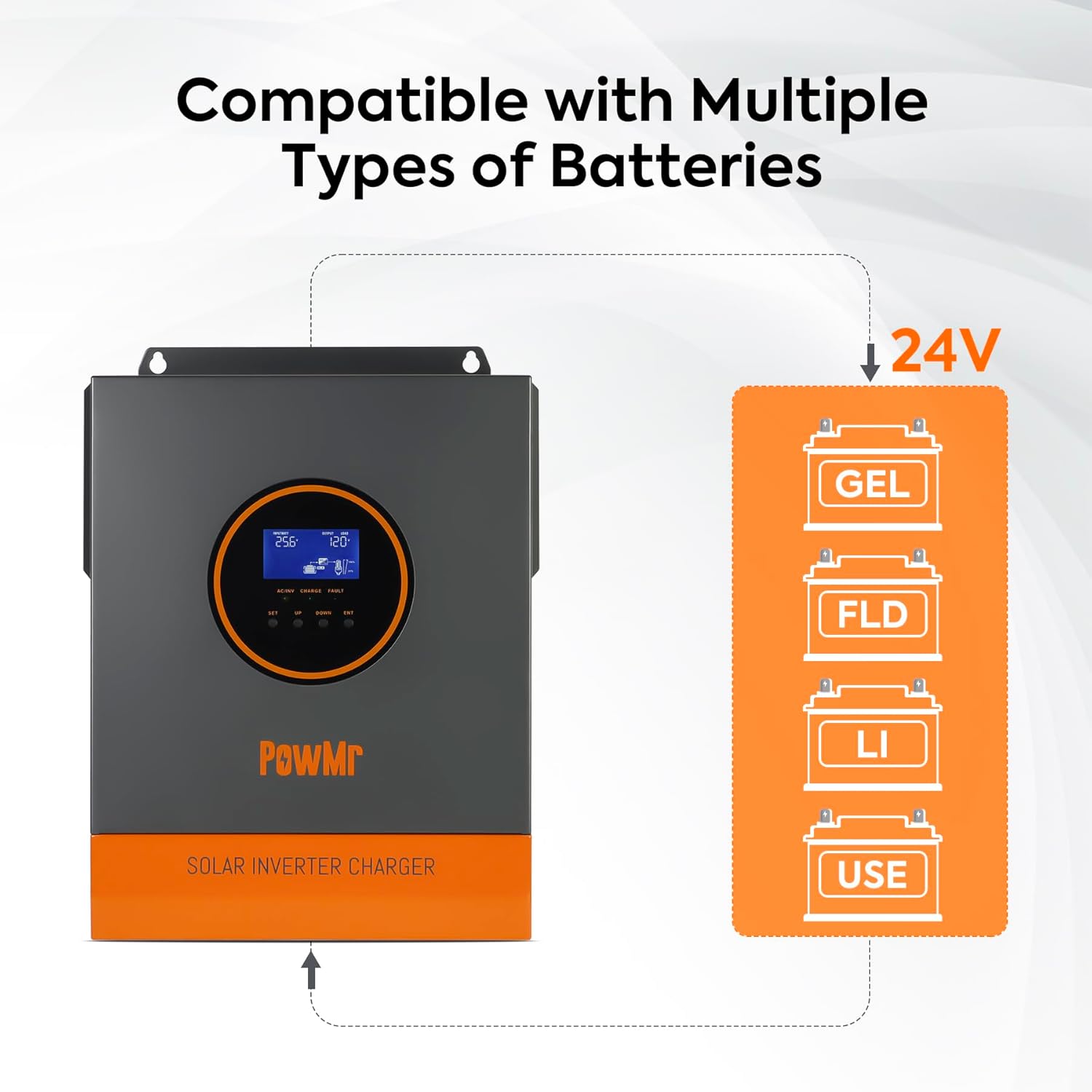
Figure 7: The inverter supports multiple 24V battery chemistries.
5.5 Remote Monitoring (Optional)
The inverter supports remote monitoring and control via the "SMARTESS" application. A separate WiFi module and GPRS data connection are required and must be purchased separately to enable this functionality.

Figure 8: Remote monitoring via the SMARTESS app with an optional WiFi module.
6. Maintenance
Regular maintenance ensures the longevity and optimal performance of your inverter.
- Cleaning: Periodically clean the exterior of the inverter, especially the cooling fans and ventilation openings, to prevent dust buildup. Use a dry cloth.
- Connections Check: Annually inspect all electrical connections for tightness and corrosion. Retighten as necessary.
- Battery Inspection: For lead-acid batteries, check electrolyte levels and terminal corrosion regularly. Follow battery manufacturer's maintenance guidelines.
- Environmental Check: Ensure the installation environment remains free from excessive dust, moisture, and extreme temperatures.
- Performance Monitoring: Regularly check the LCD display for any error codes or unusual operating parameters.
7. Troubleshooting
This section provides solutions to common issues you might encounter. For problems not listed here, contact customer support.
| Problem | Possible Cause | Solution |
|---|---|---|
| Inverter does not power on. | No battery connection, low battery voltage, ON/OFF switch off. | Check battery connections and voltage. Ensure ON/OFF switch is in "ON" position. Charge battery if voltage is too low. |
| No AC output. | Overload, short circuit, battery low, inverter fault. | Reduce load. Check for short circuits in wiring. Check battery voltage. Refer to LCD for fault codes. |
| Battery not charging from PV. | PV panels not connected, insufficient sunlight, PV voltage too low/high, charging mode setting. | Check PV connections. Ensure adequate sunlight. Verify PV voltage is within range. Check inverter's charging mode settings. |
| Battery not charging from AC. | AC input not connected, AC input voltage out of range, charging mode setting. | Check AC input connections. Verify AC input voltage. Check inverter's charging mode settings. |
| Overload warning/shutdown. | Connected loads exceed inverter capacity. | Disconnect some loads. Restart the inverter. Ensure total load is within 3200W. |
8. Technical Specifications
| Parameter | Value |
|---|---|
| Model Name | POW-LVM3.2K-24V |
| Rated Output Power | 3200W |
| AC Output Voltage | 120Vac ± 5% |
| Output Waveform | Pure Sine Wave |
| Rated Battery Input Voltage | 24Vdc (Min. starting voltage 22Vdc) |
| Max. PV Input Power | 1600W |
| Max. PV Open-Circuit Voltage | 108Vdc |
| MPPT Controller Current | 60A |
| AC Charger Current | 40A |
| Max. Hybrid Charging Current | 100A (AC charging + PV charging) |
| AC Rate Input/Output | 120Vac ± 5% |
| Compatible Battery Types | 24V Lead-Acid (Seal, AGM, Gel, Flooded), Lithium |
| Dimensions (L x W x H) | 17.72 x 14.17 x 7.48 inches (Package) |
| Item Weight | 14.5 pounds |
| Recommended Uses | Home, Office, Vehicle |
9. Warranty and Support
9.1 Warranty Information
PowMr products are designed and manufactured to high-quality standards. This product comes with a standard manufacturer's warranty against defects in materials and workmanship. Please refer to the warranty card included with your product or visit the official PowMr website for detailed warranty terms and conditions.
The warranty typically covers manufacturing defects under normal use. It does not cover damage caused by improper installation, misuse, neglect, unauthorized modifications, or natural disasters.
9.2 Customer Support
If you encounter any issues or have questions regarding the installation, operation, or maintenance of your PowMr 3200W Solar Inverter, please contact PowMr customer support. Have your model number (POW-LVM3.2K-24V) and purchase information ready when contacting support.
For the most up-to-date contact information, please visit the official PowMr website or refer to the contact details provided in your product packaging.


