Introduction
The SURAIELEC Wireless Remote Control Outlet and Light Switch Kit provides a convenient solution for controlling lighting and other electrical devices without the need for complex wiring. This kit allows for the creation of 3-way, 4-way, or 5-way switch configurations, offering flexibility in device control. The system operates using a strong RF signal, ensuring reliable performance through walls and doors.

This image illustrates the SURAIELEC wireless remote control outlet and wall switch system in a typical home environment, highlighting the flexibility of placing the switch anywhere without wiring.
Package Contents
- Wireless Remote Control Switch (Transmitter)
- Wireless Receiver Outlet
- Mounting Bracket for Remote Switch
- Mounting Hardware (screws, anchors)
- User Manual
Setup and Installation
1. Receiver Installation
The receiver is designed to be compact and plug directly into a standard wall outlet. Ensure a neutral wire is available for proper installation if replacing an existing wall switch with the rocker-style relay receiver.

A detailed view of the SURAIELEC wireless receiver, showcasing its compact dimensions (3.2 inches high, 1.4 inches deep, 2.4 inches wide), the manual program button, and the indicator light. Its design ensures the upper wall socket remains accessible.
For in-wall installation of the rocker-style relay receiver, refer to the following wiring diagram. Always ensure power is disconnected before performing any electrical work.

A wiring diagram for the 15A/1875W SURAIELEC controller, detailing connections for Line (Black), Neutral (White), and Load (Red). It also shows compatibility with standard electrical junction boxes, with receiver dimensions of 2.6 inches high, 1.4 inches wide, and 1.1 inches deep.
2. Remote Switch Installation
The wireless remote switch can be mounted anywhere using the included mounting bracket and hardware, or it can be used as a portable remote. The switch comes with a battery insulation sheet that must be removed before first use.

A visual guide demonstrating the four steps to mount the SURAIELEC wireless wall switch: 1) Secure the backplate with screws, 2) Attach the hand remote control, 3) Secure the wireless switch, and 4) Press the switch to test. Dimensions for the mounting bracket and switch are provided (3.7 inches high, 2.05 inches wide for backplate; 4.57 inches high, 2.8 inches wide, 0.67 inches deep for switch).

This image shows the SURAIELEC wireless wall switch being used as a portable remote and also mounted on a wall. It details the dimensions of the switch and mounting plate, and highlights the battery compartment with its insulation sheet, along with included hardware.
3. Pairing (Pre-Programmed & Expandable)
The kit is pre-programmed for immediate use. For additional switches or receivers, or to re-pair, follow these steps:
- Plug the receiver into a power outlet.
- Press and hold the program button on the receiver until the indicator light flashes.
- Press the ON or OFF button on the remote switch within 5 seconds.
- The receiver's indicator light will stop flashing, confirming successful pairing.
The system uses rolling/dynamic codes to prevent interference, allowing multiple kits to operate independently in the same area. You can expand your system by pairing additional SURAIELEC transmitters and receivers to create 4-way or 5-way control setups.

This diagram demonstrates the 100-foot RF remote control range, allowing signals to pass through walls and doors. It also shows various pairing configurations: multiple switches controlling one receiver, one switch controlling one receiver, and one switch controlling multiple receivers, all without interference.
Operating Instructions
Once the receiver is plugged in and paired with the remote switch, simply press the 'ON' button on the remote to turn on the connected device, and the 'OFF' button to turn it off. The strong RF signal allows control up to 100 feet away, even through walls and doors, making it ideal for various locations such as lofts, attics, stairwells, hallways, basements, and garages.

An example of the SURAIELEC wireless switch functioning as a 3-way switch in a living room, suitable for lofts, attics, stairwells, hallways, basements, and garages, allowing multiple control points without interference.
Maintenance
Battery Replacement
The remote switch is powered by a replaceable battery. If the remote's range or responsiveness decreases, it may be time to replace the battery. To replace, carefully open the battery compartment on the back of the remote switch and insert a new battery of the specified type.
Cleaning
Wipe the surfaces of the receiver and remote switch with a soft, dry cloth. Do not use liquid cleaners or abrasive materials.
Troubleshooting
- Device not turning ON/OFF:
Ensure the receiver is securely plugged into a live outlet and the connected device is properly plugged into the receiver. Verify the remote switch battery is functional and the insulation sheet has been removed. Re-pair the remote and receiver if necessary. - Reduced Remote Range:
Check the remote switch battery and replace if needed. Ensure there are no major obstructions (e.g., thick metal objects) between the remote and receiver that could significantly block the RF signal. - Interference with other devices:
The system uses rolling codes to minimize interference. If you experience issues, ensure other wireless devices are not operating on similar frequencies nearby.
Specifications
| Brand | SURAIELEC |
| Model Number (ASIN) | B0F32G4R5G |
| Input Voltage | AC 100-125V |
| Max Load (Resistive) | 10A / 1200W |
| Max Load (LED) | 200W |
| Horsepower (HP) | 1/3 HP |
| RF Range | Up to 100 ft (30 meters) |
| Control Type | Wireless RF (No Wi-Fi required) |
| Features | Pre-programmed, Expandable, No Wiring Needed for Switch Placement, Rolling Codes |
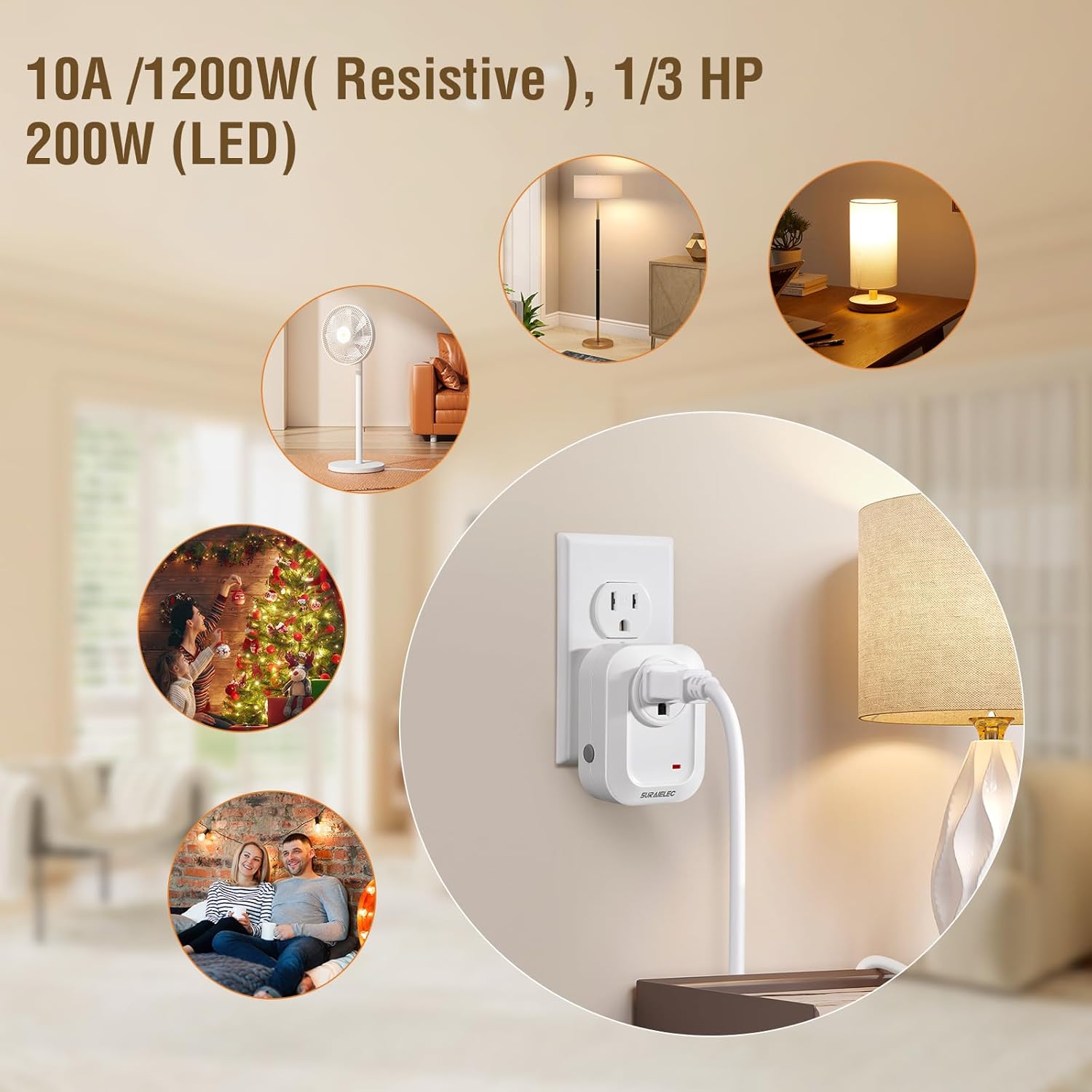
This image highlights the power capabilities of the SURAIELEC remote control outlet: 10A/1200W for resistive loads, 1/3 HP, and 200W for LED lighting. It illustrates common applications such as controlling fans, floor lamps, table lamps, and holiday lights.
Warranty and Support
The SURAIELEC Wireless Remote Control Outlet and Light Switch Kit includes a 1-year warranty. For any questions, technical assistance, or warranty claims, please contact SURAIELEC customer service. 24-hour customer service is available to assist you.