CIHATSLN RJ2S-CL-D12, RJ2S-CL-D24
Instruction Manual
CIHATSLN RJ2S-CL-D12 / RJ2S-CL-D24 8A 8-Pin Relays
Introduction
This manual provides comprehensive instructions for the safe and efficient use of your CIHATSLN RJ2S-CL-D12 and RJ2S-CL-D24 8A 8-pin relays. Please read this manual thoroughly before installation and operation to ensure proper functionality and to prevent damage or injury. Keep this manual for future reference.
Product Overview
The CIHATSLN RJ2S-CL-D12 and RJ2S-CL-D24 are general-purpose power relays designed for various industrial and automotive applications. These 8-pin relays are capable of switching up to 8 Amperes of current, providing reliable control for electrical circuits.
Key Features:
- Compact and durable design.
- High switching capacity (8A).
- 8-pin configuration for versatile connectivity.
- Available in 12V (RJ2S-CL-D12) and 24V (RJ2S-CL-D24) coil voltage options.
- Suitable for a wide range of control applications.
Product Images:
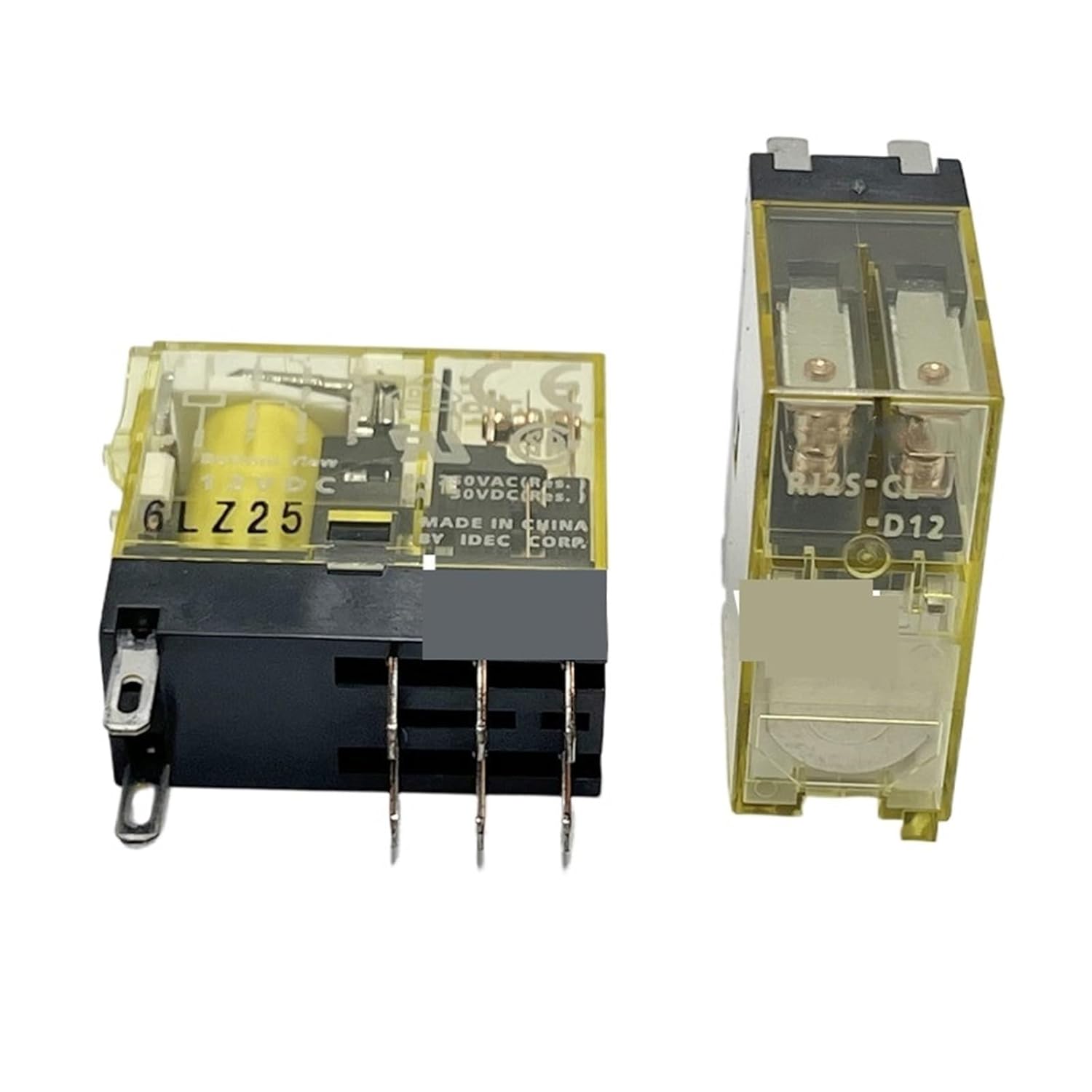
Figure 1: Front and side view of the CIHATSLN RJ2S-CL-D12 relay, highlighting its transparent casing and pin configuration.

Figure 2: Alternate view of the CIHATSLN RJ2S-CL-D12 relay, emphasizing the base and pin layout for connection.
Safety Information
Always observe the following safety precautions to prevent electric shock, fire, or damage to the product and connected equipment:
- Disconnect all power sources before installing, wiring, or servicing the relay.
- Ensure that the voltage and current ratings of the relay match the requirements of your application.
- Installation should be performed by qualified personnel familiar with electrical systems and safety standards.
- Do not exceed the specified current (8A) or voltage (D12/D24) ratings.
- Protect the relay from moisture, dust, and extreme temperatures.
- Verify all connections are secure and correct before applying power.
Setup and Installation
The RJ2S-CL-D12/D24 relays are designed for easy integration into control circuits. Follow these general steps for installation:
- Power Disconnection: Ensure all power to the circuit is disconnected before beginning installation.
- Mounting: Securely mount the relay in a suitable enclosure or on a compatible relay socket (not included). Ensure adequate ventilation.
- Wiring:
- Identify the coil terminals (A1, A2) and the contact terminals (Common, Normally Open (NO), Normally Closed (NC)). Refer to the pinout diagram typically printed on the relay or its datasheet.
- Connect the appropriate control voltage (12V DC for RJ2S-CL-D12, 24V DC for RJ2S-CL-D24) to the coil terminals.
- Wire the load circuit through the contact terminals. For example, connect the power source to the Common terminal and the load to the NO terminal for a circuit that closes when the relay is energized.
- Verification: Double-check all wiring connections for correctness and security.
- Power Application: Carefully reapply power to the circuit and test the relay's operation.
Note: Specific wiring diagrams for your application should be consulted or designed by a qualified electrician.
Operating Instructions
The RJ2S-CL-D12/D24 relays operate by energizing an electromagnetic coil, which in turn actuates a set of electrical contacts. When the rated voltage is applied to the coil, the contacts switch their state, allowing current to flow through or be interrupted in the connected load circuit.
- Energizing the Coil: Apply the specified DC voltage (12V for D12, 24V for D24) across the coil terminals. This will cause the relay to "pull in" and switch its contacts.
- De-energizing the Coil: Remove the voltage from the coil terminals. The relay will "drop out," and the contacts will return to their original state.
- Contact Operation:
- Normally Open (NO): Contacts are open when the coil is de-energized and close when the coil is energized.
- Normally Closed (NC): Contacts are closed when the coil is de-energized and open when the coil is energized.
Ensure that the load connected to the contacts does not exceed the 8A current rating to prevent damage to the relay or the circuit.
Maintenance
These relays are designed for long-term, reliable operation with minimal maintenance. However, periodic inspection can help ensure optimal performance:
- Visual Inspection: Periodically check the relay for any signs of physical damage, discoloration, or loose connections.
- Cleaning: If necessary, gently clean the exterior of the relay with a dry, soft cloth. Do not use solvents or abrasive cleaners. Ensure no dust or debris accumulates around the terminals.
- Environmental Conditions: Ensure the operating environment remains within the specified temperature and humidity ranges to prevent premature wear.
- Contact Wear: While not typically user-serviceable, excessive arcing or contact pitting can indicate an overloaded circuit or end-of-life. If such signs are observed, consider replacing the relay.
Troubleshooting
If your relay is not functioning as expected, consider the following common issues and solutions:
| Problem | Possible Cause | Solution |
|---|---|---|
| Relay does not energize (no click sound). |
|
|
| Relay energizes but load does not switch. |
|
|
| Relay overheats. |
|
|
If the problem persists after attempting these solutions, contact a qualified technician or the manufacturer for further assistance.
Specifications
| Attribute | Value |
|---|---|
| Model Numbers | RJ2S-CL-D12, RJ2S-CL-D24 |
| Brand | CIHATSLN |
| Contact Current Rating | 8 Amperes (A) |
| Number of Pins | 8 pins |
| Coil Voltage (RJ2S-CL-D12) | 12V DC |
| Coil Voltage (RJ2S-CL-D24) | 24V DC |
| Package Dimensions | 1.18 x 0.79 x 0.39 inches |
| Item Weight | 1.76 ounces (per 2PCS) |
| Manufacturer | CIHATSLN |
| First Available Date | March 29, 2025 |
Warranty and Support
For information regarding warranty coverage, technical support, or replacement parts, please contact the manufacturer, CIHATSLN, directly. Refer to your purchase documentation for specific contact details or visit the official CIHATSLN website.
It is recommended to keep your proof of purchase for warranty claims.
Related Documents - RJ2S-CL-D12, RJ2S-CL-D24
 |
FKI Kogeudstyr Pølsekogere/Vandbad CL-serie Brugervejledning Brugervejledning til FKI Pølsekogere og vandbade i CL-serien. Indeholder information om installation, drift, sikkerhed, rengøring og vedligeholdelse. |
 |
Stäubli ClipLam CL-T: 産業用スライドインコネクタ (MULTILAM技術搭載) Stäubli ClipLam CL-Tは、信頼性の高い高性能電気接続を実現するMULTILAM技術を搭載した先進の産業用コネクタです。利点、仕様、用途をご確認ください。 |
 |
FKI Sausage Cooker CL Series User Manual - Installation, Operation, and Maintenance Comprehensive user manual for FKI Fast Food Teknik's CL Series Sausage Cookers and Bain Maries. Covers installation, operation, safety, cleaning, maintenance, and technical specifications for commercial kitchen use. |
 |
VEVOR Pry Lever User Manual and Specifications Comprehensive user manual and specifications for VEVOR Pry Levers. Learn about product features, parameters, usage, and maintenance for models like CL-FZ41, CL-HL11000-70, and more. Ideal for dismantling pallets, removing flooring, and pulling nails. |
 |
Viking CL Series Wireless Analog and Digital Clocks Product Manual Comprehensive product manual for the Viking CL Series wireless analog and digital clocks. Covers CTG-2A master clock, CL-RFT transmitter/repeater, and various clock models, detailing features, applications, installation, operation, and troubleshooting for synchronized timekeeping in facilities. |
 |
VEVOR Strapping Tools User Manual and Specifications Comprehensive guide for VEVOR strapping tools, including model specifications, instructions for use, safety precautions, and maintenance. Covers models like CL-PET300, CL-PET450, CL-PP100, CL-PP1000, CL-BXG30, CL-GD180, CL-BXG60, CL-BXG120, and CL-PET600. |