1. Introduction
This manual provides detailed instructions for the installation, operation, and maintenance of your Generic X79-D8 LGA 2011 E-ATX Motherboard. Please read this manual thoroughly before proceeding with installation to ensure proper setup and to prevent damage to your components. This motherboard is designed for high-performance computing, supporting LGA 2011 processors and DDR3 memory.
2. Setup and Installation
Before beginning installation, ensure your system is powered off and disconnected from the power outlet. Handle the motherboard by its edges to avoid static discharge.
2.1 Motherboard Overview
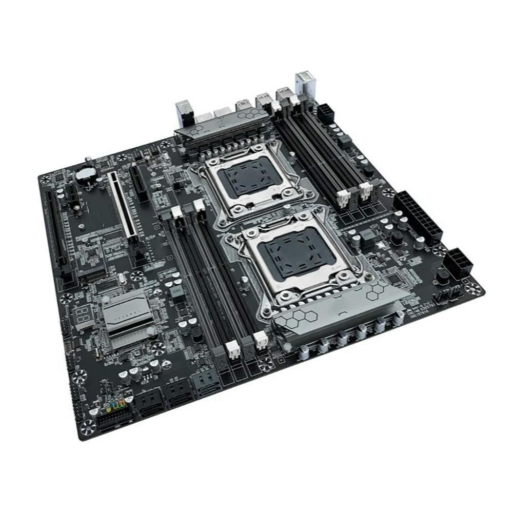
This image displays the Generic X79-D8 LGA 2011 E-ATX Motherboard from an angled top-down perspective. Key components visible include the dual LGA 2011 CPU sockets, multiple DDR3 RAM slots, PCI-E slots, SATA ports, and various power connectors and headers. The heatsinks covering the chipsets are also visible, featuring a hexagonal pattern.
2.2 CPU Installation (LGA 2011)
- Locate the LGA 2011 CPU sockets on the motherboard.
- Gently push down the load lever and pull it outwards to open the CPU socket retention frame.
- Carefully align the CPU with the socket, ensuring the triangular mark on the CPU matches the mark on the socket. Do not force the CPU into place.
- Lower the retention frame and push the load lever back into its locked position.
- Apply thermal paste to the CPU and install the CPU cooler according to its manufacturer's instructions.
2.3 Memory (RAM) Installation (DDR3)
- Locate the DDR3 DIMM slots.
- Open the clips at both ends of the DIMM slot.
- Align the memory module with the slot, ensuring the notch on the module matches the key in the slot.
- Press down firmly on both ends of the memory module until the clips snap into place.
2.4 Expansion Card Installation (PCI-E)
- Identify the appropriate PCI-E slot for your expansion card (e.g., graphics card, network card).
- Remove the corresponding slot cover from your PC case.
- Align the expansion card with the PCI-E slot and press down firmly until it is securely seated.
- Secure the card to the case with a screw or retention clip.
2.5 Power Connections
- 24-pin ATX Power Connector: Connect the main power supply cable to this connector.
- 8-pin CPU Power Connector: Connect the CPU power cable from your power supply to this connector. Ensure both CPU sockets receive power if using dual CPUs.
2.6 Storage Device Connections
- Connect SATA data cables from your storage devices (HDDs, SSDs) to the SATA ports on the motherboard.
- Ensure your power supply provides power to these devices.
2.7 Front Panel Connectors
Connect the cables from your PC case's front panel (power button, reset button, USB ports, audio jacks, LED indicators) to the corresponding headers on the motherboard. Refer to the motherboard's silkscreen labels for correct pin assignments.
3. Operating Instructions
3.1 Initial Boot-Up
- After all components are installed and connected, connect your monitor, keyboard, and mouse.
- Connect the power cord to your power supply and turn on the power switch.
- Press the power button on your PC case.
- The system should power on, and you should see a display on your monitor.
3.2 BIOS/UEFI Access
During the initial boot sequence, repeatedly press the DEL or F2 key (or as indicated on screen) to enter the BIOS/UEFI setup utility. Here you can configure system settings, boot order, and monitor hardware status.
3.3 Driver Installation
After installing your operating system, install the necessary drivers for the motherboard's chipsets, network, audio, and any other integrated components. These drivers are typically provided on a support CD or can be downloaded from the manufacturer's website.
4. Maintenance
- Dust Cleaning: Regularly clean dust from inside your PC case, especially from CPU coolers, GPU fans, and motherboard surfaces, using compressed air. Ensure the system is powered off and unplugged before cleaning.
- BIOS Updates: Periodically check the manufacturer's website for BIOS/UEFI updates. Updates can improve stability, compatibility, and performance. Follow the update instructions carefully to avoid system damage.
- Component Checks: Ensure all cables are securely connected and that no components are loose.
5. Troubleshooting
If you encounter issues, consider the following basic troubleshooting steps:
- No Power: Check all power connections (24-pin ATX, 8-pin CPU, power supply switch, wall outlet).
- No Display: Ensure the monitor is connected to the graphics card (not the motherboard's integrated graphics, if applicable). Reseat the graphics card and RAM modules.
- System Beeps: Refer to your motherboard's beep code guide (often found on the manufacturer's website) to diagnose POST errors.
- System Instability: Check CPU and GPU temperatures. Ensure drivers are up to date. Test memory modules individually.
- Component Not Detected: Reseat the component. Check its power and data connections. Verify it is enabled in BIOS/UEFI.
6. Specifications
| Feature | Specification |
|---|---|
| Brand | Generic |
| Model | X79-D8 |
| CPU Socket | LGA 2011 (Dual Sockets) |
| Memory Type | DDR3 |
| Max Memory Capacity | Up to 512GB |
| PCI-E Version | 3.0 |
| Form Factor | E-ATX |
| Item Model Number | 6189411334561 |
7. Warranty and Support
Specific warranty details for this Generic X79-D8 motherboard are not provided in the product information. For warranty claims, technical support, or further assistance, please refer to the documentation included with your purchase or contact the vendor/manufacturer directly.