1. Introduction
This manual provides essential information for the safe and efficient installation, operation, and maintenance of the HVGZDQQD Directional Valve SD2E-B4. Please read this manual thoroughly before using the product to ensure proper function and to prevent damage or injury. This valve is a 4/2 directional valve, solenoid operated, spool type, and direct acting, designed for controlling the direction of fluid flow in hydraulic systems.
2. Safety Information
- Always ensure that installation, maintenance, and repair work are performed by qualified and authorized personnel.
- Before any work on the hydraulic system, ensure that the system is depressurized and secured against accidental startup.
- Wear appropriate personal protective equipment (PPE) such as safety glasses and gloves.
- Do not exceed the maximum operating pressure or temperature specified for the valve.
- Ensure electrical connections are made correctly and conform to local electrical codes. Disconnect power before working on electrical components.
- Use only hydraulic fluids compatible with the valve's seals and materials.
- Keep the work area clean and free from obstructions.
3. Product Overview
The HVGZDQQD SD2E-B4 is a high-performance directional control valve designed for robust industrial applications. It features a compact design and is engineered for precise control of hydraulic fluid direction.
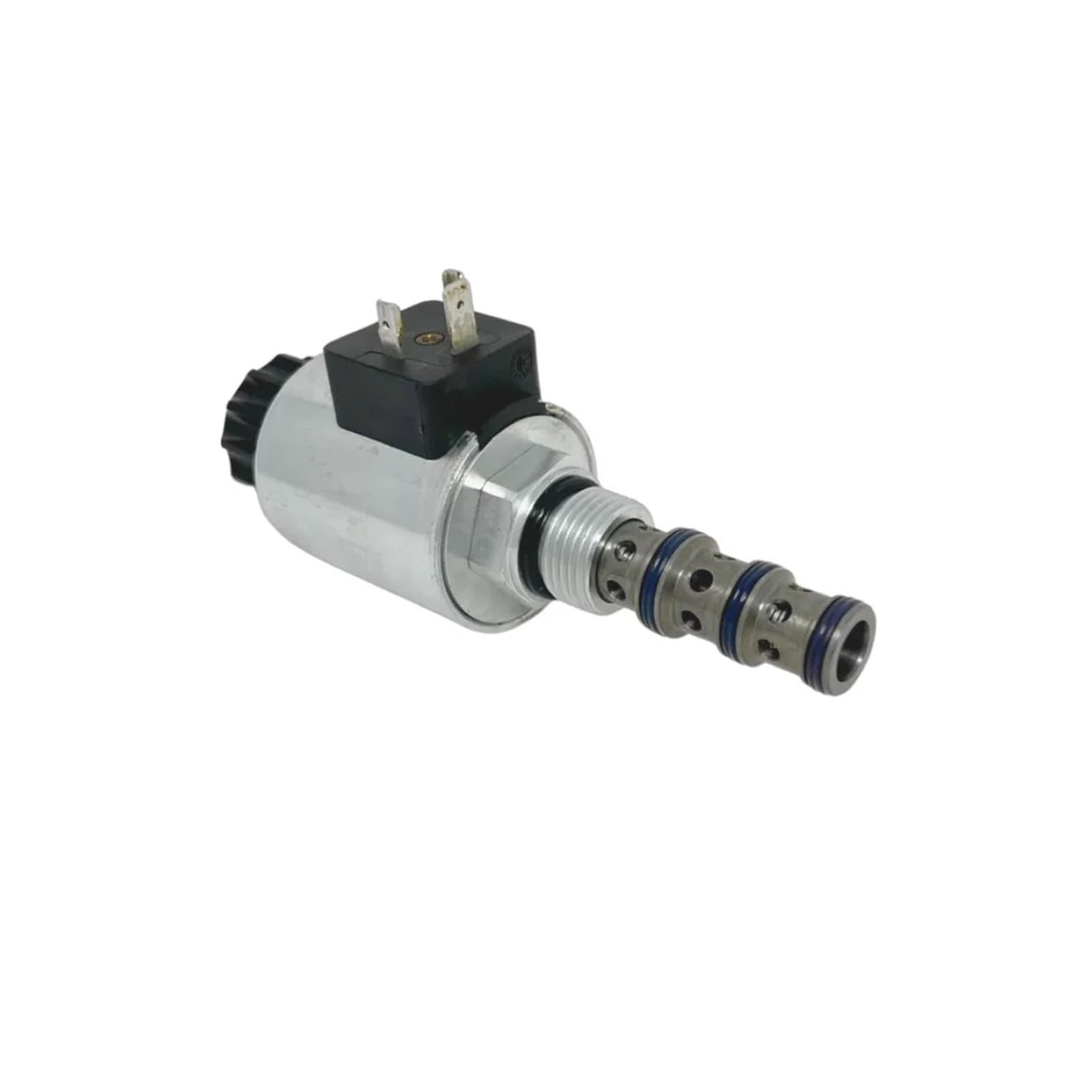
Figure 3.1: HVGZDQQD Directional Valve SD2E-B4. This image shows the complete valve assembly, including the solenoid coil and the spool section.

Figure 3.2: Alternate view of the HVGZDQQD Directional Valve SD2E-B4, highlighting the electrical connector and the valve body.
3.1 Technical Features
- Hardened precision parts for durability.
- High flow capacity for efficient operation.
- High transmitted hydraulic power.
- Wide range of manual overrides available.
- All ports may be fully pressurized.
- Variety of optional spools available.
- Coil interchangeable with existing SD*-B* product line.
- Standard version zinc-coated with surface protection according to ISO 9227 (240 h salt spray).
3.2 Functional Description
The SD2E-B4 is a 4-way, 2-position high-pressure directional spool valve in the form of a screw-in cartridge. The valve is used mainly to direct flow to actuators. It operates by a solenoid which shifts the spool to control the fluid path.

Figure 3.3: Internal diagram of the Lightline valve, showing the spool (1), seals (2, 3), and spring (4) components within the valve body.
4. Technical Data
The following table provides detailed technical specifications for the SD2E-B4 valve.

Figure 4.1: Technical Data Sheet for SD2E-B4 Valve, including features, functional description, and detailed technical specifications.
| Parameter | Value | Unit |
|---|---|---|
| Max flow | 40 (Lightline) / 50 (High performance) | l/min (GPM) |
| Max operating pressure | 350 (5100) | bar (PSI) |
| Operating temperature range (NBR) | -30 to +100 (-22 to +212) | °C (°F) |
| Fluid temperature range (FPM) | -20 to +120 (-4 to +248) | °C (°F) |
| Ambient temperature range | -30 to +60 (-22 to +140) | °C (°F) |
| Supply voltage tolerance | ±10 | % |
| Max. switching frequency | 15000 | 1/h |
| Weight without coil | 0.25 (0.55) | kg (lbs) |
| Valve cavity | 7/8-14 UNF (C-10-4) | |
| Surface treatment (Standard) | Zinc-coated (ZnCr-3), ISO 9227 (240 h) | |
| Surface treatment (Optional) | Zinc-coated (ZnNi), ISO 9227 (520 h) |
5. Dimensions and Manual Override
The physical dimensions of the valve and available manual override options are detailed below.

Figure 5.1: Dimensions in millimeters (inches) for both Lightline and High performance versions, along with various manual override options and the ordering code structure.
5.1 Dimensions
Refer to Figure 5.1 for detailed dimensional drawings. Key dimensions include:
- Overall length (Lightline): 60.45 mm (2.38 inches)
- Overall length (High performance): 60.45 mm (2.38 inches)
- Thread size: 7/8-14 UNF-2A
- Hex size: 27 mm
5.2 Manual Override Options
The valve can be equipped with different manual override options:
- No designation (Standard): Basic operation without a specific manual override mechanism.
- Designation M2 (Rubber boot protected): Features a rubber boot for protection, providing a manual override function.
- Designation M5 (Socket head screw, size 2.5): Manual override via a socket head screw.
- Designation M9 (Without manual override): No manual override function is present.
In case of solenoid malfunction or power failure, the spool of the valve can be shifted by manual override under the condition that the pressure in the back line does not exceed 25 bar (363 PSI). For alternative manual overrides, contact technical support.
6. Operating Limits
Understanding the operating limits is crucial for the longevity and performance of the valve. Refer to Figure 4.1 for graphical representations of operating limits and pressure drop.
6.1 Operating Limits - Lightline
This graph illustrates the relationship between operating pressure (bar/PSI) and flow (l/min / GPM) for the Lightline version at 60 °C (140 °F) ambient temperature and 10% undervoltage (UN -10%).
6.2 Operating Limits - High Performance
This graph shows the operating pressure (bar/PSI) versus flow (l/min / GPM) for the High performance version at 50 °C (122 °F) ambient temperature and 10% undervoltage (UN -10%).
6.3 Pressure Drop Related to Flow Rate
This graph details the pressure drop (bar/PSI) across the valve in relation to the flow rate (l/min / GPM) for both Lightline and High performance models. Different curves represent various connections (e.g., 1-2, 1-3, 3-4, 2-4).
7. Setup and Installation
Proper installation is critical for the valve's performance and safety. Ensure all components are clean and free from debris before assembly.
- Valve Cavity: The SD2E-B4 valve is designed for a 7/8-14 UNF (C-10-4) valve cavity. Ensure the manifold or block has the correct cavity for proper fitment.
- Cleanliness: Maintain extreme cleanliness during installation. Contaminants can severely impact valve performance and lifespan.
- Mounting: Screw the cartridge valve into the prepared valve cavity. Apply the recommended torque to ensure a secure, leak-free seal. Refer to the system manufacturer's specifications for torque values.
- Port Connections: Connect hydraulic lines to the appropriate ports (P, A, B, T) as indicated by the hydraulic schematic of your system. Double-check all connections for tightness.
- Electrical Connection: Connect the solenoid coil to the power supply according to the system's electrical diagram. Ensure the voltage and current match the coil specifications.
- System Bleeding: After installation, bleed the hydraulic system to remove any trapped air.
8. Operation
The SD2E-B4 is a solenoid-operated, spool-type, direct-acting directional valve. Its primary function is to control the direction of hydraulic fluid flow.
- Solenoid Activation: When the solenoid is energized, it generates a magnetic force that acts directly on the valve spool.
- Spool Movement: This force causes the spool to shift from its de-energized (rest) position to the energized position.
- Flow Direction Change: The movement of the spool reconfigures the internal passages of the valve, directing hydraulic fluid to different ports (e.g., from P to A and B to T, or vice versa), thereby controlling the movement of an actuator.
- De-energized State: When the solenoid is de-energized, a return spring typically pushes the spool back to its original rest position, changing the flow path back to its initial configuration.
Refer to the functional symbols in Figure 5.1 for specific spool configurations (e.g., 2Z11, 2Z51, 2X21) and their corresponding flow paths.
9. Maintenance
Regular maintenance ensures optimal performance and extends the lifespan of the valve.
- Fluid Quality: Regularly check the hydraulic fluid for contamination and degradation. Use only clean, recommended hydraulic fluid. Replace fluid and filters according to system manufacturer guidelines.
- Leakage Inspection: Periodically inspect the valve and connections for any signs of external leakage. Tighten connections as necessary, but do not overtighten.
- Solenoid Inspection: Check the solenoid coil for any signs of damage, overheating, or loose connections.
- Seal Replacement: Over time, seals may wear out. If internal or external leakage persists, the seals within the valve may need to be replaced by qualified personnel using genuine spare parts.
- Cleaning: Keep the exterior of the valve clean to prevent dirt and debris from entering the system.
10. Troubleshooting
If the valve is not functioning correctly, consult the following troubleshooting guide. For complex issues, contact qualified service personnel.
| Problem | Possible Cause | Solution |
|---|---|---|
| Valve does not shift (no flow) | No electrical power to solenoid; Faulty solenoid coil; Spool jammed by contamination; Incorrect pressure. | Check electrical connections and power supply; Test/replace solenoid coil; Clean or replace valve; Verify system pressure. |
| Reduced flow or pressure | Partial spool shift; Contamination restricting flow; Worn valve components. | Check solenoid and electrical supply; Clean valve; Inspect and replace worn parts. |
| External leakage | Loose connections; Damaged seals; Incorrect torque. | Tighten connections to specified torque; Replace damaged seals; Ensure proper installation. |
| Erratic or inconsistent operation | Air in hydraulic system; Contaminated fluid; Intermittent electrical fault. | Bleed the system; Replace fluid and filters; Check electrical connections and wiring. |
11. Specifications
Detailed specifications for the HVGZDQQD Directional Valve SD2E-B4.
| Specification | Value |
|---|---|
| Model Number | SD2E-B4 |
| Manufacturer | HVGZDQQD |
| ASIN | B0F2YMJ4NK |
| Package Dimensions | 1.18 x 0.79 x 0.39 inches |
| Item Weight | 7.1 ounces |
| Assembly Required | No |
| Number of Pieces | 1 |
12. Ordering Information
The ordering code for the SD2E-B4 valve allows for customization based on specific requirements. Refer to Figure 5.1 for the complete ordering code structure.
The basic model is SD2E-B4. Additional options are specified by appending codes for:
- Valve Cavity: 7/8-14 UNF (C-10-4)
- Performance Level: Lightline (L) or High performance (H)
- Functional Symbol: e.g., 2Z11, 2Z51, 2X21
- Surface Treatment: A (zinc-coated ZnCr-3) or B (zinc-coated ZnNi)
- Seals: NBR (standard) or FPM (Viton)
- Manual Override: No designation (standard), M2 (rubber boot protected), M5 (socket head screw), M9 (without manual override)
Example ordering code structure: SD2E-B4 / [Functional Symbol] - [Surface Treatment] - [Seals] - [Manual Override]
13. Warranty and Support
For warranty information, technical support, or spare parts, please contact your HVGZDQQD supplier or authorized service center. Ensure you have the product model number (SD2E-B4) and purchase details available when seeking support.