CLXDKLKEQ YH-TCN4S
YH-TCN4S Temperature Controller User Manual
Model: YH-TCN4S | Brand: CLXDKLKEQ
Introduction
This manual provides detailed instructions for the installation, operation, and maintenance of the CLXDKLKEQ YH-TCN4S Dual Output SSR Relay Temperature Controller. This high-precision digital display controller is designed for accurate temperature adjustment in various applications.
The YH-TCN4S supports K, J, T, and CU50 type thermocouples and operates on 100-240VAC. It features a digital display for both process value (PV) and set value (SV), with a maximum measuring temperature of 400°C.
Product Overview

Setup and Installation
1. Mounting
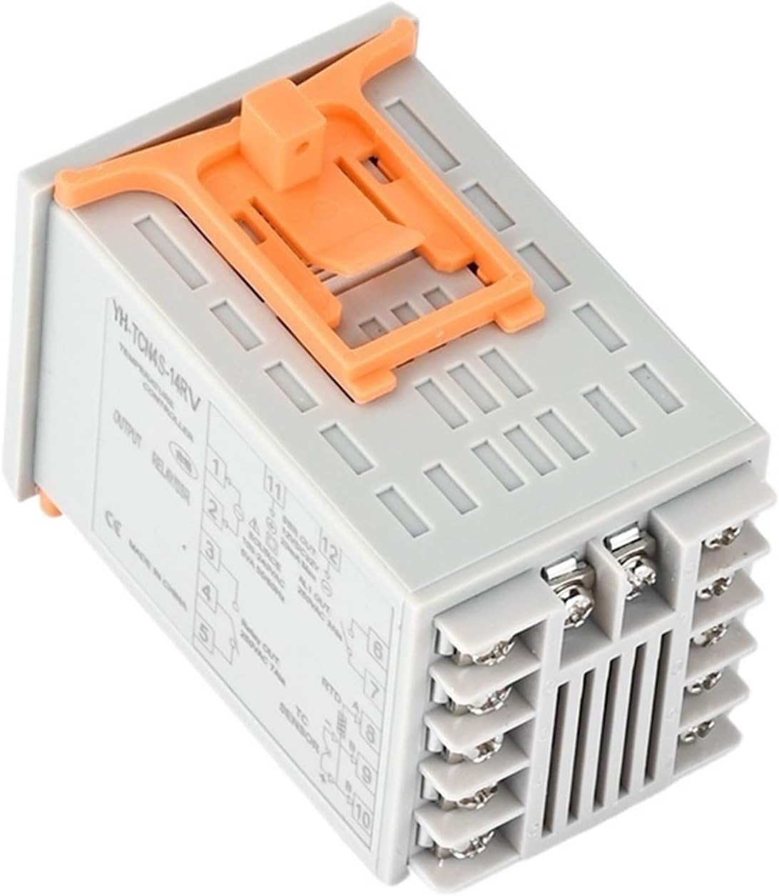
The YH-TCN4S is designed for panel mounting. Ensure adequate space for ventilation and wiring. Secure the controller using the provided mounting brackets.
2. Wiring Connections
Refer to the wiring diagram on the side of the unit and Figure 3 for correct connections. Ensure all power is disconnected before wiring.
- Power Supply: Connect 100-240VAC to terminals 1 and 2.
- SSR Output: Connect to terminals 11 and 12 (12VDC, 20mA Max).
- Relay Output: Connect to terminals 3 and 4 (250VAC 3A).
- Sensor Input: Connect your K, J, T, or CU50 type thermocouple/RTD sensor to terminals 8, 9, and 10 as per sensor type.
Caution: Incorrect wiring can damage the unit or cause electrical hazards. Consult a qualified electrician if unsure.
Operation
1. Power On
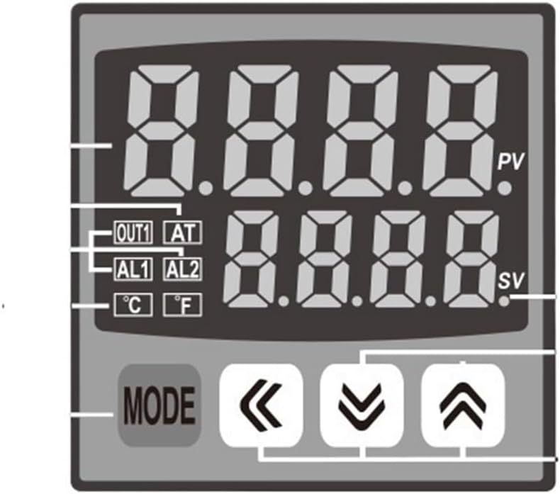
Once wired correctly, apply power. The display will show the current Process Value (PV) and Set Value (SV).
2. Setting the Temperature (SV)
- Press the MODE button briefly to enter the SV setting mode. The SV display will flash.
- Use the Up Arrow (▲) and Down Arrow (▼) buttons to adjust the desired temperature.
- Use the Left Arrow (◀) button to shift the cursor for faster adjustment of specific digits.
- Press the MODE button again to confirm the setting and exit the SV setting mode.
3. Advanced Settings (Parameter Menu)
To access advanced parameters (e.g., PID settings, alarm settings, input type), press and hold the MODE button for approximately 3-5 seconds. Navigate through parameters using the MODE button and adjust values using the arrow keys.
Refer to the full technical datasheet for a complete list of parameters and their functions.
Maintenance
- Cleaning: Keep the controller clean and free from dust. Use a soft, dry cloth for cleaning the display and casing. Do not use abrasive cleaners or solvents.
- Inspection: Periodically inspect wiring connections to ensure they are secure and free from corrosion.
- Environment: Ensure the operating environment remains within the specified temperature and humidity ranges to prevent damage.
- Sensor Check: If temperature readings are erratic, check the sensor and its connections for damage or loose wiring.
Always disconnect power before performing any maintenance.
Troubleshooting
| Problem | Possible Cause | Solution |
|---|---|---|
| No display/No power | No power supply; Incorrect wiring; Blown fuse (external) | Check power source (100-240VAC); Verify wiring connections; Check external fuse. |
| Erratic temperature readings | Sensor faulty; Loose sensor connection; Incorrect sensor type setting | Replace sensor; Secure sensor wiring; Verify sensor type in advanced settings. |
| Output not activating | SV not reached; Output mode incorrect; Wiring issue | Ensure PV is below SV (for heating); Check output mode (e.g., PID, ON/OFF); Verify output wiring. |
| Display shows "HHHH" or "LLLL" | Sensor open circuit (HHHH); Sensor short circuit (LLLL) | Check sensor and wiring for breaks or shorts; Replace sensor if damaged. |
For issues not listed, please contact customer support.
Specifications
- Model: YH-TCN4S
- Input Type: K, J, T, CU50 Thermocouple/RTD
- Measuring Range: 0-400°C (Max 120°C & Above, specific range depends on sensor)
- Power Supply: 100-240VAC
- Output 1 (SSR): 12VDC, 20mA Max
- Output 2 (Relay): 250VAC 3A
- Display Type: Digital (PV & SV)
- Display Size: 1.9 Inches & Under
- Item Weight: 1.76 ounces
- Manufacturer: CLXDKLKEQ
Warranty and Support
For warranty information, please refer to the purchase documentation or contact your retailer. For technical support, please reach out to CLXDKLKEQ customer service through the contact information provided at the point of purchase.
Return Policy: The product is subject to a 30-day refund/replacement policy as per the seller's terms.