1. Introduction
This manual provides detailed instructions for the installation, operation, and maintenance of the FCNGEVBH TC3-501T PID Temperature Controller. This device is designed for precise temperature control in various industrial and commercial applications, featuring PID control, timer functions, and a relay output.
2. Safety Information
Read all instructions carefully before installation and operation. Failure to follow these instructions may result in equipment damage, personal injury, or electric shock.
- Ensure the power supply voltage matches the controller's specifications (AC100-220V).
- Disconnect power before performing any wiring or maintenance.
- All wiring should be performed by qualified personnel in accordance with local electrical codes.
- Do not operate the controller in environments with excessive moisture, dust, or corrosive gases.
- Avoid exposing the device to strong vibrations or impacts.
3. Product Overview
The TC3-501T is a compact and versatile PID temperature controller with digital displays for set value (SV) and process value (ST), along with various indicator lights and control buttons.

This image displays the front panel of the TC3-501T PID Temperature Controller. It features two digital displays for Set Value (SV) and Current Temperature (ST), along with indicator lights for output (OUT), alarm (AL), and auto-tuning (AT). Control buttons include up/down arrows for adjustment, and dedicated buttons for 'TEMP' and 'TIME' settings.

This image shows three models of FCNGEVBH PID Temperature Controllers: TC3-401T, TC3-501T, and TC3-701T. While they share similar functionality and display layouts, their physical dimensions and specific features may vary. The TC3-501T is visible in the foreground, demonstrating its compact design.
Front Panel Components:
- SV Display: Shows the Set Value (target temperature).
- ST Display: Shows the Current Temperature (process value).
- OUT Indicator: Illuminates when the output relay is active.
- AT Indicator: Illuminates during auto-tuning process.
- AL Indicator: Illuminates when an alarm condition is met.
- TEMP Button: Used to access and adjust temperature-related settings.
- TIME Button: Used to access and adjust timer-related settings.
- Up/Down Arrows: Used to increase or decrease parameter values.
4. Specifications
| Parameter | Value |
|---|---|
| Model | TC3-501T |
| Power Supply | 100-240VAC 50/60Hz |
| Temperature Range | K-type 0~400 ℃ |
| Output Type | Relay |
| Display Type | Digital |
| Display Size | 1.9 Inches & Under |
| Usage | Industrial |
| Item Weight | 1.76 ounces |
| Package Dimensions | 1.18 x 0.79 x 0.39 inches |
5. Setup and Installation
5.1 Mounting
The TC3-501T is designed for embedded panel mounting. Ensure adequate space for ventilation and access to wiring terminals. Refer to the product's physical dimensions for precise panel cutout requirements.
5.2 Wiring
Proper wiring is critical for the safe and correct operation of the controller. Refer to the wiring diagram below and ensure all connections are secure.
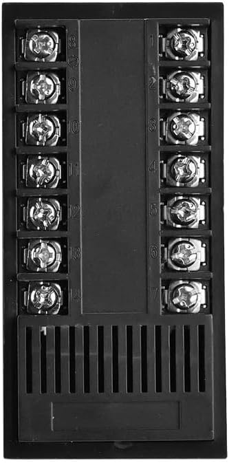
This image illustrates the rear wiring terminals of the FCNGEVBH TC3-501T PID Temperature Controller. The terminals are clearly numbered from 1 to 14, indicating connection points for power supply, sensor input, and relay output. Proper wiring according to the provided diagram is crucial for safe and correct operation.
General Wiring Guidelines:
- Power Supply: Connect the AC100-220V power supply to the designated terminals (typically L and N).
- Sensor Input: Connect the K-type thermocouple to the sensor input terminals, observing polarity.
- Output Relay: Connect the controlled device (e.g., heater, fan) to the relay output terminals. Ensure the load current does not exceed the relay's maximum rating.
- Use appropriate wire gauges for all connections.
6. Operating Instructions
6.1 Power On
After completing all wiring, apply power to the controller. The displays will illuminate, showing the current temperature (ST) and the set value (SV).
6.2 Setting Temperature (SV)
- Press the TEMP button. The SV display will begin to flash.
- Use the Up and Down arrow buttons to adjust the desired temperature.
- Press the TEMP button again or wait a few seconds for the setting to be saved and the display to stop flashing.
6.3 Setting Timer
The TC3-501T includes a timer function. Specific timer modes and settings may vary. Consult the full product manual for advanced timer configurations.
- Press the TIME button. The timer display will flash.
- Use the Up and Down arrow buttons to set the desired time duration.
- Press the TIME button again or wait for the setting to be saved.
6.4 PID Auto-Tuning
For optimal temperature control, PID auto-tuning may be required. This process automatically calculates the best PID parameters for your specific heating system.
- To initiate auto-tuning, typically press and hold the TEMP button for a few seconds until the AT indicator illuminates.
- The controller will cycle the output to determine system characteristics. This process can take some time.
- Once complete, the AT indicator will turn off, and the new PID parameters will be saved.
7. Maintenance
Regular maintenance ensures the longevity and reliable operation of your TC3-501T controller.
- Cleaning: Wipe the front panel with a soft, dry cloth. Do not use abrasive cleaners or solvents.
- Inspection: Periodically check wiring connections for looseness or damage. Ensure the thermocouple is securely connected and free from corrosion.
- Ventilation: Ensure the ventilation slots on the controller are not obstructed to prevent overheating.
8. Troubleshooting
If you encounter issues with your TC3-501T controller, refer to the following common problems and solutions:
| Problem | Possible Cause | Solution |
|---|---|---|
| Controller does not power on | No power supply; incorrect wiring | Check power connections and voltage. Verify wiring according to the diagram. |
| Temperature reading is inaccurate or shows 'HHHH'/'LLLL' | Sensor disconnected or faulty; incorrect sensor type | Check thermocouple connection and ensure it is a K-type. Replace if faulty. |
| Output not activating | Incorrect SV setting; faulty relay; wiring issue | Verify SV is set correctly. Check output wiring. Test the relay if possible. |
| Temperature overshoots/undershoots | PID parameters not optimized | Perform PID auto-tuning (Section 6.4). |
9. Warranty and Support
FCNGEVBH products are manufactured to high-quality standards. For warranty information, technical support, or service inquiries, please contact your retailer or the manufacturer directly. Keep your purchase receipt as proof of purchase.