1. Introduction
This manual provides essential information for the safe and effective installation, operation, and maintenance of the DeWin 2P AC 230V 40A Automatic Reclosing Circuit Breaker (Type A). Please read this manual thoroughly before installation and use, and retain it for future reference.
2. Safety Information
WARNING: Installation of this device must only be performed by qualified professionals. Improper installation can lead to electric shock, fire, or other serious injury.
- Always disconnect power at the main supply before installing or servicing the circuit breaker.
- Ensure all wiring complies with local and national electrical codes.
- Do not operate the device if it is damaged or malfunctioning.
- Verify correct voltage and current ratings before connection.
- The device is designed for indoor use in environments within the specified ambient temperature range.
3. Product Overview
The DeWin 2P AC 230V 40A Automatic Reclosing Circuit Breaker is an intelligent device designed to automatically restore power after an accidental trip, reducing manual intervention and improving system efficiency. It features a digital display for real-time status monitoring and offers both automatic and manual operating modes.

Figure 3.1: Overview of the DeWin Automatic Reclosing Circuit Breaker.
3.1 Key Features
- Intelligent Automatic Reclosing: Automatically restores power when the Miniature Circuit Breaker (MCB) trips accidentally, minimizing downtime.
- Automatic/Manual Switching: Allows selection between automatic remote control and manual operation.
- LED Digital Display: A 3-digit display shows critical information such as voltage, number of trips, and fault status.
- LED Indicator: Green for normal operation, red for MCB overcurrent fault.
- Robust Construction: Made from PC material with an IP20 protection grade.
- DIN Rail Installation: Designed for easy mounting on a 35mm DIN rail.
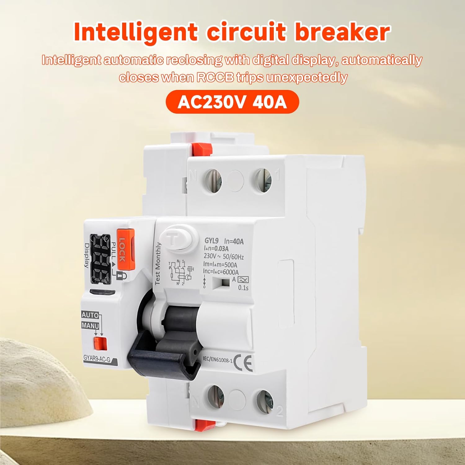
Figure 3.2: Key features of the 2P intelligent automatic reclosing device, highlighting PC material, IP20 protection, DIN rail installation, digital display, two switching modes, and LED indicator.
3.2 Component Identification

Figure 3.3: Labeled components of the circuit breaker, including the leakage switch, safety lock, broken code display, LED digital display, working mode selection switch (AUTO/MANU), operating handle, and product number.
- Leakage Switch: The main circuit breaker component.
- Safety Lock: Prevents accidental operation. Pull to unlock.
- Broken Code Display: 3-digit LED display for status and fault codes.
- LED Digital Display: Provides visual feedback on device status.
- Working Mode Selection (AUTO/MANU): Switch to select operating mode.
- Operating Handle: Manual control for ON/OFF.
- Product Number: Model identification.
4. Specifications

Figure 4.1: Product dimensions, showing a width of 49mm for the main unit, 54mm total width, 82mm height, and 35mm depth.
| Parameter | Value |
|---|---|
| Brand | DEWIN |
| Model Number | QDXCXDQDC-GS99306-02 |
| Material | PC |
| Operating Voltage | 230V AC |
| Rated Current | 40A |
| Working Frequency | 50/60 Hz |
| Control Signal | Automatic reclosing + dry contact control |
| Digital Display | 3-digit display (voltage, trip count, fault status) |
| Effective Control Signal Duration | > 400ms |
| Closing Action Time | < 1s |
| Opening Action Time | < 0.5s |
| Control Loop Cable Length | ≤ 1500m |
| Power Consumption (Static) | ≤ 1.5 VA |
| Power Consumption (Dynamic) | ≤ 25 VA |
| Rated Insulation Voltage | 400V |
| Rated Impulse Withstand Voltage (Uimp) | 4 kV (4.9 kV at sea level) |
| Self-locking Protection | 3 reclosures in 10s / 4 reclosures in 20s / 6 reclosures in 30s; automatically locks after 40s, recovers automatically. |
| Electrical Life | 10,000 cycles (3 times/minute) |
| Mechanical Life | 10,000 cycles |
| Indicator Light | Green (normal), Red (MCB overcurrent fault) |
| Automatic/Manual Switching | Remote automatic available; remote manual disabled in MANU mode. |
| Protection Level | IP20 |
| Ambient Temperature | -25℃ to +70℃ |
| Storage Temperature | -40℃ to +70℃ |
| Wiring Capacity (Power/Control Terminals) | 28-12AWG 2.5 mm² |
| Wiring Capacity (Auxiliary Signal Terminals) | 28-14AWG 1.5 mm² |
| Mounting | DIN rail EN 60715 (35mm) |
| Weight | 350 g |
| Circuit Breaker Type | RCD |
| Number of Poles | 2 |
4.2 Waveform Definition

Figure 4.2: Table detailing waveform definitions and action ranges for Sinusoidal AC, Pulsating DC, Pulsating half-wave + DC, High frequency, Two-phase full-wave rectification, Three-phase full-wave rectification, and DC for both AC type and A type circuit breakers.
5. Setup and Installation
Installation must be performed by a qualified electrician. Ensure all power is disconnected before proceeding.
5.1 Mounting
The circuit breaker is designed for mounting on a standard 35mm DIN rail (EN 60715).
- Securely attach the circuit breaker to the DIN rail in the desired position within the electrical panel.
- Ensure adequate ventilation around the device.
5.2 Wiring Diagram
Follow the wiring diagram carefully. Incorrect wiring can cause damage to the device or electrical system.

Figure 5.1: Detailed wiring diagram showing connections for Line (L), Neutral (N), and load circuits. It also illustrates the connection of external control buttons (opening and closing) to the auxiliary terminals.
Important Notes for Wiring:
- The product does not require an external button for automatic reclosing.
- When manually controlling the opening and closing of the switch, an external button control is required.
- A normally open self-reset button is used for external control; other button types are not applicable.

Figure 5.2: Close-up view of the green terminal block for control signal connections, showing individual screw terminals.
Connect the control signal wires (28-12AWG 2.5 mm² for power/control, 28-14AWG 1.5 mm² for auxiliary) to the designated terminals as shown in the wiring diagram.
6. Operating Instructions
6.1 Mode Selection (AUTO/MANU)
Use the switch labeled "AUTO/MANU" on the device to select the desired operating mode.
- AUTO Mode: In this mode, the circuit breaker will automatically attempt to reclose after a fault trip. Remote control switching is available.
- MANU Mode: In this mode, the circuit breaker must be manually reset after a fault trip. Remote control switching is disabled.

Figure 6.1: Explanation of AUTO and MANU modes and corresponding LED digital display behavior. In AUTO mode, red flashing indicates opening, green flashing indicates closing. In MANU mode, a yellow light is always on for manual opening and closing. The display shows the number of opening and closing times and the countdown for closing recovery.
Note: After the "LOCK" switch is turned on, the circuit breaker cannot be closed to protect the safety of electricity and prevent accidental touch.
6.2 Digital Display and Indicator Light
The 3-digit LED display provides real-time information:
- Voltage: Current operating voltage.
- Trip Count: Number of times the circuit breaker has tripped.
- Fault Status: Indicates the type of fault.
The indicator light provides quick visual status:
- Green Light: Normal operation.
- Red Light: MCB overcurrent fault.
6.3 Automatic Reclosing Logic (Self-Locking Mode)
In AUTO mode, the device attempts to reclose after a fault. If the fault persists, it enters a self-locking protection sequence:
- First Fault: The circuit breaker automatically recloses after 9 seconds.
- Second Fault: The circuit breaker automatically recloses after 59 seconds.
- Third Fault: The circuit breaker automatically recloses after 299 seconds.
- Fourth Fault: After the fourth consecutive fault, the circuit breaker enters a self-locking mode. Manual intervention is required to check the circuit safety and manually reclose the breaker. The device will recover automatically after 40 seconds if the fault is cleared.

Figure 6.2: Visual representation of the self-locking mode, showing the increasing delay times (9s, 59s, 299s) for automatic reclosing after successive faults, and the final self-lock state.
6.4 Tripped Count Zero Reset
To reset the tripped counter to zero:
- Pull out the "LOCK" mechanism.
- Perform three quick operations (e.g., toggle the operating handle) within 0 seconds (this implies a very rapid sequence). Refer to the device markings for precise execution.
7. Maintenance
The DeWin Automatic Reclosing Circuit Breaker is designed for minimal maintenance. However, regular checks are recommended to ensure optimal performance and safety.
- Visual Inspection: Periodically inspect the device for any signs of physical damage, discoloration, or loose connections.
- Cleaning: Keep the device clean and free from dust and debris. Use a dry, soft cloth for cleaning. Do not use liquid cleaners.
- Test Button: Press the "Test Monthly" button (if present) as recommended by electrical safety standards to verify the RCD's functionality.
- Professional Check: For any concerns or complex issues, consult a qualified electrician.
8. Troubleshooting
If the circuit breaker is not functioning as expected, refer to the following troubleshooting guide:
| Problem | Possible Cause | Solution |
|---|---|---|
| Device does not reclose in AUTO mode after a trip. | Persistent fault in the circuit; device is in self-locking mode. | Check the digital display for fault codes. Manually inspect the circuit for the cause of the fault. Clear the fault, then manually reclose the breaker. |
| Digital display shows an error code. | Indicates a specific fault condition (e.g., overcurrent, leakage). | Refer to the device's specific error code definitions (if available on the device itself or in supplementary documentation) to diagnose and resolve the issue. |
| Device does not power on. | No power supply; incorrect wiring. | Verify that the main power supply is active. Check all wiring connections according to the diagram in Section 5.2. |
| Cannot switch to MANU mode or remote control is unresponsive. | Incorrect mode selection; wiring issue for remote control. | Ensure the AUTO/MANU switch is correctly positioned. Check wiring for remote control signals. |
9. Warranty and Support
For warranty information and technical support, please contact your retailer or the manufacturer directly. Keep your purchase receipt as proof of purchase.