WWEIFUS YWQ-1442
WWEIFUS YWQ-1442 High Pressure Hydraulic Hand Calibration Pump User Manual
Model: YWQ-1442 | Brand: WWEIFUS
1. Introduction
This manual provides detailed instructions for the safe and effective operation, setup, and maintenance of the WWEIFUS YWQ-1442 Portable Hydraulic Hand Calibration Pump. This device is designed as an auxiliary tool for testing and calibrating pressure instruments such as pressure (differential pressure) transmitters, precision pressure gauges, pressure sensors, and pressure switches. Its portable design makes it suitable for both on-site and laboratory use, providing stable pressure for accurate measurements.
2. Product Overview and Components
The WWEIFUS YWQ-1442 is a robust and portable hydraulic pressure source. Familiarize yourself with its main components before operation.
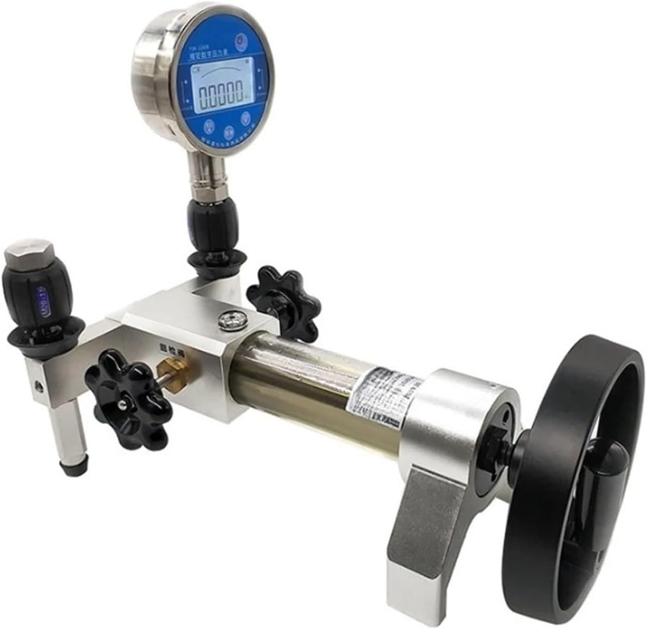
Figure 2.1: Overall view of the WWEIFUS YWQ-1442 Portable Hydraulic Hand Calibration Pump, showing the main pump body, pressure gauge, and handwheel.
- Pump Body: The central unit containing the hydraulic mechanism.
- Pressure Gauge Connection: Point for attaching a standard pressure gauge (not included with "Only Pump" variant).
- Test Port (M20x1.5): Connection point for the instrument under calibration.
- Handwheel: Used to generate and adjust hydraulic pressure.
- Fine Adjustment Valve: For precise pressure control.
- Release Valve: To release pressure from the system.

Figure 2.2: Detail of the M20x1.5 test port, indicating the standard thread size for connecting instruments.
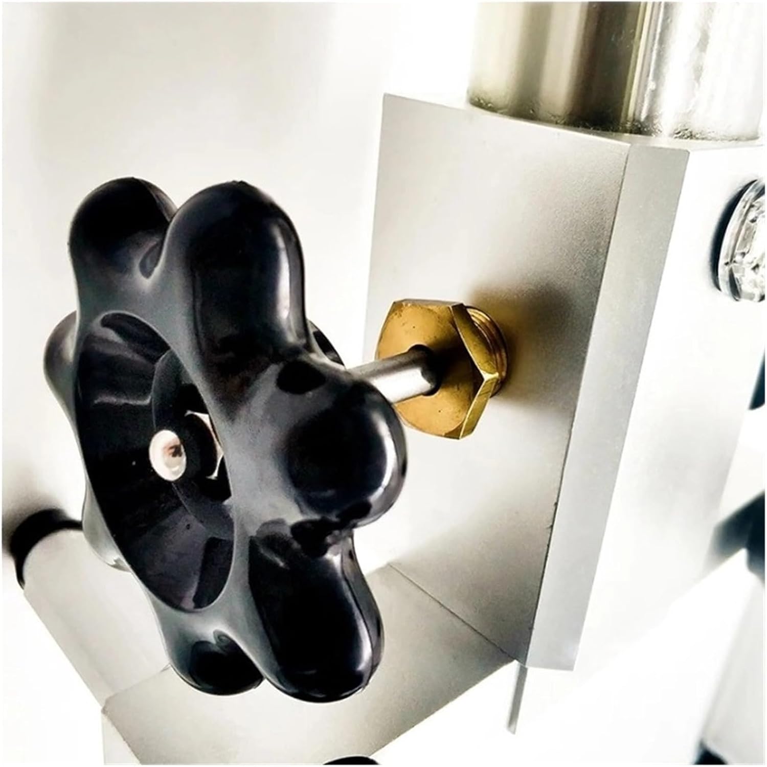
Figure 2.3: Close-up of an adjustment knob, likely for fine pressure control or valve operation.

Figure 2.4: Detail of the handwheel, used for manual pressure generation.
3. Technical Specifications
| Parameter | Value |
|---|---|
| Product Name | Portable Hydraulic Pump |
| Model | YWQ-1442 |
| Pressure Range | 0-70 MPa (0-700 Bar) |
| Medium | Oil & Water |
| Structure | Manual |
| Minimum Adjustable Pressure | 10 KPa |
| Dimensions | 450 x 290 x 280 mm (Approximate) |
| Material | Stainless Steel |
4. Safety Information
Always observe the following safety precautions to prevent injury and damage to the equipment:
- Read this manual thoroughly before operating the pump.
- Ensure all connections are secure and leak-free before applying pressure.
- Do not exceed the maximum rated pressure of 70 MPa (700 Bar).
- Use only compatible hydraulic oil or clean water as the pressure medium.
- Wear appropriate personal protective equipment (PPE), such as safety glasses, when operating the pump.
- Never point pressurized connections towards yourself or others.
- Release pressure slowly and carefully after each calibration.
- Keep the pump clean and free from debris.
- Store the pump in a dry, safe place away from extreme temperatures.
5. Setup and Preparation
- Unpacking: Carefully remove the pump from its packaging and inspect for any signs of damage.
- Placement: Place the pump on a stable, level surface.
- Fluid Filling:
- Ensure the release valve is open.
- Fill the reservoir with the appropriate hydraulic fluid (oil or clean water) to the recommended level. Avoid overfilling.
- Close the release valve.
- Connect Reference Gauge: Screw your calibrated reference pressure gauge into the designated pressure gauge connection port. Ensure a tight, leak-free seal.
- Connect Device Under Test (DUT): Connect the instrument to be calibrated (DUT) to the M20x1.5 test port. Use appropriate adapters if necessary and ensure all connections are secure.
- Bleeding Air: Before applying pressure, operate the handwheel a few times with the release valve slightly open to purge any air from the system. Close the release valve once fluid flows smoothly without air bubbles.
6. Operating Instructions
Follow these steps for accurate pressure generation and calibration:
- Initial Pressure Generation: Slowly turn the handwheel clockwise to begin generating pressure. Observe both the reference gauge and the DUT.
- Coarse Adjustment: Continue turning the handwheel until the pressure is slightly below your target calibration point.
- Fine Adjustment: Use the fine adjustment valve (if present, typically a smaller knob) to precisely increase or decrease the pressure to the desired calibration point. Turn clockwise to increase, counter-clockwise to decrease.
- Stabilization: Allow the pressure to stabilize for a few moments before taking readings from both the reference gauge and the DUT.
- Record Readings: Record the readings from both instruments.
- Repeat: Repeat the process for all required calibration points.
- Pressure Release: Once all measurements are complete, slowly open the release valve counter-clockwise to gradually reduce the pressure in the system to zero. Do not open abruptly.
- Disconnect: Once pressure is fully released, disconnect the DUT and the reference gauge.
7. Maintenance
Regular maintenance ensures the longevity and accuracy of your calibration pump.
- Fluid Replacement: Periodically replace the hydraulic fluid (oil or water) to ensure cleanliness and prevent contamination. The frequency depends on usage and fluid type.
- Cleaning: Keep the exterior of the pump clean. Wipe down with a soft, damp cloth. Avoid using harsh chemicals.
- Inspection: Regularly inspect all connections, hoses, and seals for wear, damage, or leaks. Replace any worn components immediately.
- Storage: When not in use, store the pump in a clean, dry environment, preferably with the pressure released and the reservoir cap securely closed.
8. Troubleshooting
| Problem | Possible Cause | Solution |
|---|---|---|
| Pump does not generate pressure. |
|
|
| Pressure drops quickly. |
|
|
| Difficulty achieving target pressure. |
|
|
9. Contact and Support
For technical assistance, warranty information, or to order replacement parts, please contact WWEIFUS customer support through your original point of purchase or visit the official WWEIFUS website.
Please retain this manual for future reference.
Ask a question about this manual
Ask about setup, troubleshooting, compatibility, parts, safety, or missing instructions. Manuals+ will review the question and use this page’s manual context to help answer it.