1. Introduction
The TAREMRJXISA Aneng ST212 is a versatile digital clamp meter designed for accurate measurement of various electrical parameters. This device combines the functions of a clamp meter and a multimeter, allowing for non-contact AC/DC current measurement, as well as traditional measurements of AC/DC voltage, resistance, capacitance, frequency, temperature, and continuity. It features a 6000-count display for precise readings and includes essential functions like Non-Contact Voltage (NCV) detection and True RMS measurement, making it suitable for a wide range of electrical testing applications.
2. Safety Information
To ensure safe operation and prevent damage to the meter, please read and understand all safety instructions before use. Failure to observe these warnings could result in serious injury or death.
- Always adhere to local and national safety codes.
- Do not exceed the maximum input limits for any function.
- Ensure the rotary switch is in the correct position for the desired measurement before connecting test leads.
- Use caution when working with voltages above 30V AC RMS, 42V peak, or 60V DC, as these pose a shock hazard.
- Inspect test leads for damaged insulation or exposed metal before use. Replace if damaged.
- Do not operate the meter if it appears damaged or if the case is open.
- Remove test leads from the circuit before changing functions or ranges.
- Replace batteries when the low battery indicator appears to ensure accurate readings.
3. Product Features
- High-Quality Components: Constructed with reliable electronic components for consistent and long-lasting performance.
- User-Friendly Design: Engineered for ease of use, featuring clear instructions and straightforward operation.
- Versatile Applications: Suitable for a variety of electrical testing scenarios, including industrial, automotive, and general household electronics.
- 6000 Counts Display: Provides high-resolution measurements for enhanced accuracy.
- AC/DC Current Measurement: Non-contact current measurement via the clamp jaw.
- AC/DC Voltage Measurement: Standard voltage testing capabilities.
- Resistance, Capacitance, Frequency, Temperature: Comprehensive multimeter functions.
- Non-Contact Voltage (NCV) Detection: Safely detect live wires without direct contact.
- True RMS Measurement: Accurate readings for non-sinusoidal waveforms.
- Data Hold Function: Freezes the displayed reading for convenient recording.
- Relative Measurement (REL): Measures the difference between a stored value and a new measurement.
4. Package Contents
Please check the package contents upon receipt to ensure all items are present:
- TAREMRJXISA Aneng ST212 Digital Clamp Meter
- Test Leads (one pair)
- K-Type Thermocouple (Temperature Probe)
- User Manual
- Carrying Pouch (optional, may vary by package)
5. Device Layout
Familiarize yourself with the components of your Aneng ST212 Digital Clamp Meter:
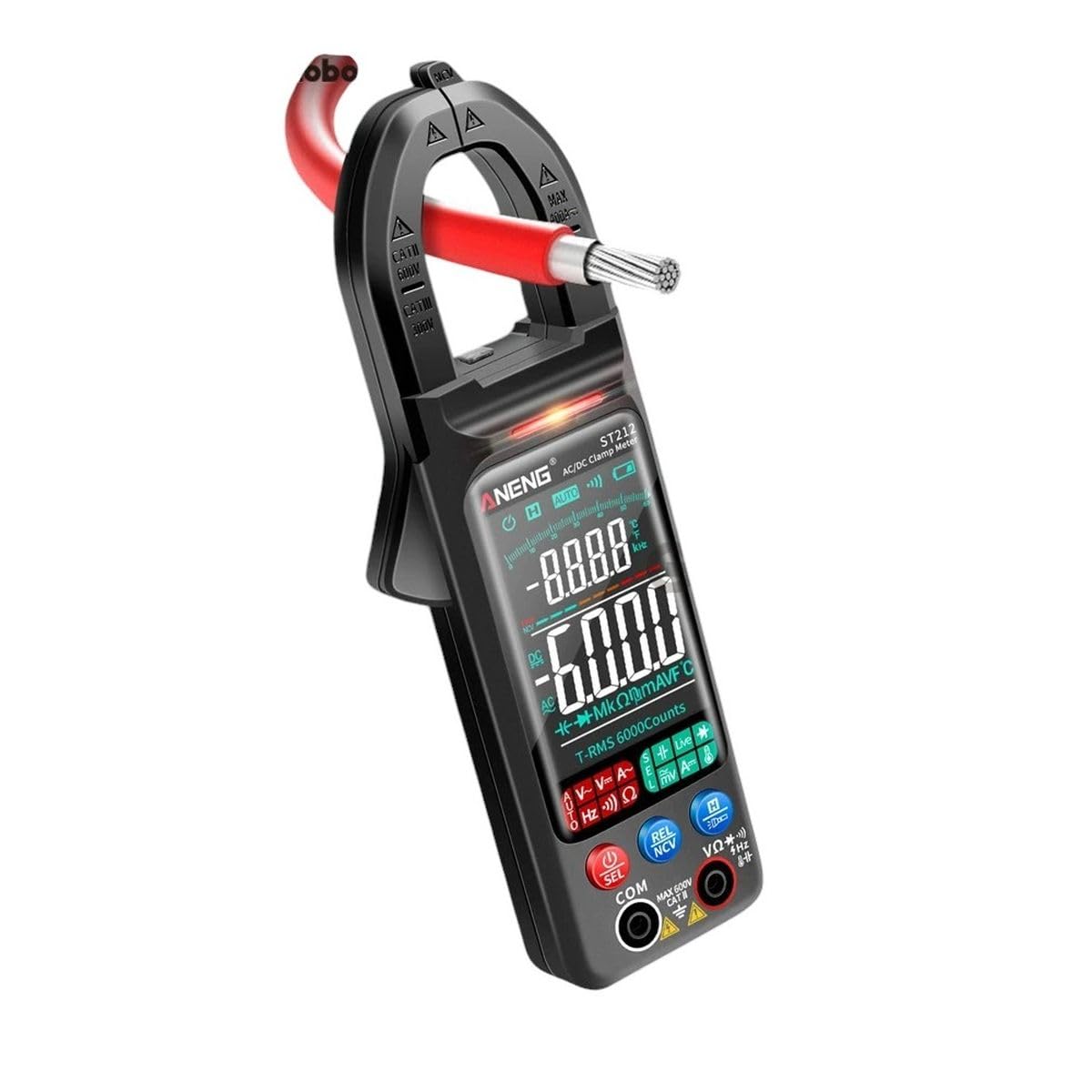
Image showing the front view of the TAREMRJXISA Aneng ST212 Digital Clamp Meter. The device is black with a red clamp jaw. The display shows '6000' and various measurement symbols. Buttons for 'SEL', 'NCV', 'REL', and 'HOLD' are visible below the display. Input jacks for test leads are located at the bottom.
- Clamp Jaw: Used for non-contact AC/DC current measurement.
- NCV Sensor: Detects non-contact voltage.
- Flashlight: Illuminates the measurement area.
- Display: Shows measurement readings, units, and indicators.
- Function Rotary Switch: Selects the desired measurement function.
- Function Buttons: Include SEL (Select), REL (Relative), NCV (Non-Contact Voltage), and HOLD (Data Hold).
- Input Jacks: For connecting test leads (COM, VΩHzCAPTemp, A).
6. Setup
6.1. Battery Installation
- Locate the battery compartment cover on the back of the meter.
- Use a screwdriver to open the cover.
- Insert the required batteries (typically AAA, refer to the compartment label) observing the correct polarity (+/-).
- Replace the battery compartment cover and secure it with the screw.
6.2. Connecting Test Leads
For most measurements (voltage, resistance, continuity, etc.), connect the test leads as follows:
- Insert the black test lead into the COM (common) jack.
- Insert the red test lead into the VΩHzCAPTemp jack.
- For current measurements using test leads (if applicable, not clamp), refer to specific instructions for the 'A' jack.
7. Operating Instructions
7.1. Power On/Off
Turn the rotary switch from the 'OFF' position to any desired measurement function to power on the meter. To power off, turn the rotary switch back to 'OFF'.
7.2. Function Selection
Rotate the central dial to select the desired measurement function (e.g., V~ for AC Voltage, V- for DC Voltage, A~ for AC Current, Ω for Resistance). Some positions may have multiple functions; press the 'SEL' button to cycle through them.
7.3. AC/DC Current Measurement (Clamp)
- Set the rotary switch to the AC Current (A~) or DC Current (A-) position.
- Open the clamp jaw by pressing the trigger.
- Enclose only one conductor (wire) within the clamp jaw. Ensure the jaw is fully closed.
- Read the current value on the display.
7.4. AC/DC Voltage Measurement
- Connect the black test lead to the COM jack and the red test lead to the VΩHzCAPTemp jack.
- Set the rotary switch to the AC Voltage (V~) or DC Voltage (V-) position.
- Touch the test probes to the circuit points where voltage is to be measured (in parallel with the load).
- Read the voltage value on the display.
7.5. Resistance Measurement
- Connect the test leads as described for voltage measurement.
- Set the rotary switch to the Resistance (Ω) position.
- Ensure the circuit or component under test is de-energized.
- Touch the test probes across the component or circuit to measure resistance.
- Read the resistance value on the display.
7.6. Continuity Test
- Connect the test leads as described for voltage measurement.
- Set the rotary switch to the Continuity (usually shared with Resistance/Diode, press 'SEL' if needed) position.
- Ensure the circuit or component under test is de-energized.
- Touch the test probes across the component or circuit.
- A continuous beep indicates a complete circuit (continuity). The display will show a low resistance value.
7.7. Diode Test
- Connect the test leads as described for voltage measurement.
- Set the rotary switch to the Diode Test (usually shared with Resistance/Continuity, press 'SEL' if needed) position.
- Ensure the diode is de-energized.
- Touch the red probe to the anode and the black probe to the cathode of the diode. The display will show the forward voltage drop.
- Reverse the probes. The display should show 'OL' (Open Line) for a good diode.
7.8. Capacitance Measurement
- Connect the test leads as described for voltage measurement.
- Set the rotary switch to the Capacitance (CAP) position.
- Ensure the capacitor is fully discharged before testing.
- Touch the test probes across the capacitor terminals.
- Read the capacitance value on the display.
7.9. Frequency Measurement
- Connect the test leads as described for voltage measurement.
- Set the rotary switch to the Frequency (Hz) position.
- Touch the test probes to the circuit where frequency is to be measured.
- Read the frequency value on the display.
7.10. Temperature Measurement
- Ensure the meter is off.
- Connect the K-type thermocouple to the input jacks, observing polarity (usually red to VΩHzCAPTemp, black to COM).
- Set the rotary switch to the Temperature (°C/°F) position.
- Place the thermocouple tip on the object or in the environment to be measured.
- Read the temperature value on the display.
7.11. Non-Contact Voltage (NCV) Detection
- Set the rotary switch to the NCV position or press the NCV button if it's a dedicated function.
- Move the NCV sensor (located at the top of the clamp jaw) close to the conductor or outlet.
- If AC voltage is detected, the meter will emit an audible beep and/or flash an indicator light.
7.12. Data Hold Function
Press the 'HOLD' button to freeze the current reading on the display. Press it again to release the hold and resume live measurements.
7.13. REL (Relative Measurement) Function
Press the 'REL' button to store the current reading as a reference value. Subsequent measurements will display the difference between the current reading and the stored reference. Press 'REL' again to exit relative mode.
8. Maintenance
8.1. Cleaning
Wipe the meter's case with a damp cloth and a mild detergent. Do not use abrasives or solvents. Ensure the meter is completely dry before use.
8.2. Battery Replacement
When the low battery indicator appears on the display, replace the batteries promptly to ensure accurate operation. Refer to Section 6.1 for battery installation instructions.
8.3. Storage
If the meter is not used for an extended period, remove the batteries to prevent leakage and damage. Store the meter in a cool, dry place, away from direct sunlight and extreme temperatures.
9. Troubleshooting
This section addresses common issues you might encounter with your clamp meter.
| Problem | Possible Cause | Solution |
|---|---|---|
| No display or weak display | Dead or low batteries; Incorrect battery polarity; Meter off. | Replace batteries; Check battery orientation; Turn rotary switch to a function. |
| Inaccurate readings | Low battery; Incorrect function/range selected; Poor test lead contact; External interference. | Replace batteries; Select appropriate function/range; Ensure good contact; Move away from strong electromagnetic fields. |
| No continuity beep | Circuit is open; Meter not in continuity mode; Test leads faulty. | Check circuit for breaks; Select continuity function; Test leads for damage. |
| 'OL' (Overload) displayed | Input value exceeds selected range; Open circuit (for resistance/continuity). | Select a higher range; Check for open circuit. |
10. Specifications
The following are the general specifications for the TAREMRJXISA Aneng ST212 Digital Clamp Meter:
| Parameter | Value |
|---|---|
| Display | 6000 Counts |
| AC Current (Clamp) | Range: 0-600A; Accuracy: ±(2.5%+5 digits) |
| DC Current (Clamp) | Range: 0-600A; Accuracy: ±(2.5%+5 digits) |
| AC Voltage | Range: 0-600V; Accuracy: ±(1.0%+3 digits) |
| DC Voltage | Range: 0-600V; Accuracy: ±(0.5%+3 digits) |
| Resistance | Range: 0-60MΩ; Accuracy: ±(1.0%+3 digits) |
| Capacitance | Range: 0-60mF; Accuracy: ±(4.0%+5 digits) |
| Frequency | Range: 0-10MHz; Accuracy: ±(1.0%+3 digits) |
| Temperature | Range: -20°C to 1000°C (-4°F to 1832°F); Accuracy: ±(2.5%+5 digits) |
| Diode Test | Yes |
| Continuity | Yes, with buzzer |
| NCV (Non-Contact Voltage) | Yes |
| True RMS | Yes |
| Power Supply | 2 x 1.5V AAA Batteries (not included) |
| Manufacturer | TAREMRJXISA |
| Model | ST212 |
| Date First Available | March 26, 2025 |
11. Warranty and Customer Support
TAREMRJXISA is committed to providing high-quality products and excellent customer service. While specific warranty details are not provided in this manual, we encourage you to retain your proof of purchase for any warranty claims. For technical assistance, troubleshooting beyond this manual, or general inquiries, please contact TAREMRJXISA customer support through your purchase platform or the contact information provided with your product packaging.