ZKRZCGXZ STC-3008 DC 12V
User Manual: STC-3008/STC-3018/STC-3028 Dual Digital Temperature Humidity Controller
Model: STC-3008 DC 12V
1. Introduction
This manual provides detailed instructions for the installation, operation, and maintenance of your ZKRZCGXZ STC-3008/STC-3018/STC-3028 Dual Digital Temperature and Humidity Controller. This device is designed for precise control of temperature and humidity in various applications, ensuring optimal environmental conditions. Please read this manual thoroughly before use to ensure safe and correct operation.
2. Product Features
- Dual Display: Simultaneous display of real-time temperature and humidity.
- High Accuracy: Provides precise temperature and humidity readings with 0.1 Celsius accuracy.
- NTC Sensor Probe: Equipped with a reliable NTC sensor for accurate measurements.
- Wide Measurement Range: Temperature measuring range from -55°C to 120°C.
- Relay Output: 10A relay output for controlling external heating/cooling or humidifying/dehumidifying devices.
- Versatile Power Supply: Supports DC 12V (for this model), DC 24V, and AC 110/220V variants.
3. Safety Information
To prevent injury or damage to the device, please observe the following safety precautions:
- Always disconnect power before performing any wiring or maintenance.
- Ensure the power supply voltage matches the controller's specified voltage (DC 12V for this model).
- Strictly distinguish between the relay, sensor, and power interfaces during wiring to avoid short circuits or damage.
- Ensure the sensor down-lead and power wire are kept at a proper distance to prevent interference.
- Do not expose the device to water, excessive moisture, or corrosive environments.
- Installation should be performed by qualified personnel if you are unsure about electrical wiring.
4. Setup and Installation
4.1 Wiring Diagram
Refer to the diagram below for proper wiring connections. Ensure all connections are secure and correct before applying power.

Figure 1: Wiring diagram for the STC-3018 controller. Terminals 1 and 2 are for power supply (DC 12V for this model). Terminals 3 and 4 are for the NTC temperature/humidity sensor. Terminals 5, 6, 7, and 8 are for the 10A/220VAC output relay connections.
4.2 Connection Steps
- Power Supply: Connect your DC 12V power source to terminals 1 and 2. Observe polarity if applicable.
- Sensor Connection: Connect the NTC sensor probe to terminals 3 and 4. The sensor is non-polar, so connection order does not matter.
- Output Control: Connect your heating/cooling or humidifying/dehumidifying device to terminals 5, 6, 7, and 8 as per your application's requirements. These terminals are for the 10A relay output.
Note: Double-check all wiring before powering on the device to prevent damage.
5. Operating Instructions
5.1 Display and Buttons Overview

Figure 2: Front panel of the STC-3018 controller. The left display shows temperature, and the right display shows humidity. Buttons include 'Set', 'Up', 'Down', and 'Rst'.
- Left Display (Red): Shows current temperature.
- Right Display (Blue): Shows current humidity.
- OUT Indicator: Lights up when the relay output is active.
- °C/°F Indicator: Shows the current temperature unit.
- Set Button: Used to enter and exit parameter setting mode.
- Up (▲) Button: Increases values or navigates through parameters.
- Down (▼) Button: Decreases values or navigates through parameters.
- Rst Button: Resets settings or exits certain modes.
5.2 Setting Parameters
The controller allows you to set various parameters for temperature and humidity control. Specific parameter codes (e.g., P0, P1) and their functions are typically detailed in a more comprehensive manual. However, the general process involves:
- Enter Setting Mode: Press and hold the Set button for a few seconds until the display changes, indicating entry into parameter setting mode.
- Navigate Parameters: Use the Up (▲) and Down (▼) buttons to scroll through different parameter codes (e.g., for setting temperature start/stop, humidity start/stop, calibration, etc.).
- Adjust Value: Once a parameter code is selected, press the Set button again to enter its value adjustment mode. Use the Up (▲) and Down (▼) buttons to change the value.
- Confirm and Save: Press the Set button again to confirm the value and move to the next parameter, or wait a few seconds for the device to automatically save and exit the setting mode.
- Exit Setting Mode: Press the Rst button or wait for the device to automatically exit after a period of inactivity.
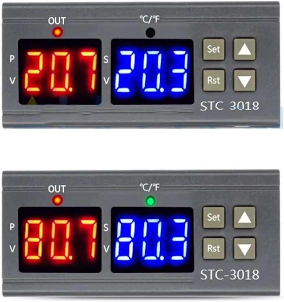
Figure 3: Examples of temperature and humidity readings on the STC-3018 controller's dual display.
6. Maintenance
Regular maintenance helps ensure the longevity and accuracy of your controller:
- Cleaning: Wipe the unit's surface with a soft, dry cloth. Do not use abrasive cleaners or solvents.
- Sensor Inspection: Periodically check the NTC sensor probe for any physical damage or corrosion. Ensure it is clean and free from debris that might affect readings.
- Ventilation: Ensure the controller has adequate ventilation, especially if installed in an enclosed space, to prevent overheating.
7. Troubleshooting
| Problem | Possible Cause | Solution |
|---|---|---|
| Display is blank or not powering on. | No power supply; incorrect wiring; faulty unit. | Check power connections (terminals 1 & 2). Ensure power supply matches DC 12V. Verify wiring. |
| Incorrect temperature/humidity readings. | Sensor not connected; faulty sensor; sensor placed incorrectly. | Check sensor connection (terminals 3 & 4). Inspect sensor for damage. Ensure sensor is in the environment to be measured. |
| Controller not switching output (OUT light not activating). | Output wiring incorrect; set parameters are outside current readings; relay fault. | Verify output wiring (terminals 5-8). Check your set temperature/humidity thresholds and differentials. Ensure the current readings are within the range that should trigger the output. |
| "Err" or other error codes displayed. | Sensor open circuit; sensor short circuit; out of range. | Check sensor connections. Replace sensor if damaged. Ensure measured values are within the device's operating range. |
8. Technical Specifications
| Parameter | Value |
|---|---|
| Model Number | Digital Thermostat Temperature Controller (STC-3008 DC 12V) |
| Temperature Measuring Range | -55~120 Celsius |
| Accuracy | 0.1 Celsius |
| Power Supply | DC12V (for this specific model) |
| Sensor Error Delay | 1 Minute |
| Power Consumption | <3W |
| Sensor Type | NTC sensor |
| Storage Temperature | -30-75 Celsius |
| Relative Humidity | 20-85% (No condensate) |
| Sensor Length | 1 Meter (including the probe) |
| Product Size | 75x34.5x85(mm) |
| Item Weight | 1.76 ounces (approx. 50 Grams) |
| Package Dimensions | 1.18 x 0.79 x 0.39 inches |
9. Warranty Information
Specific warranty details for this product are not provided in the available information. Please refer to the seller's or manufacturer's warranty policy at the time of purchase or contact them directly for warranty claims and information.
10. Customer Support
For technical assistance, troubleshooting beyond this manual, or product inquiries, please contact the seller or manufacturer directly through the platform where the product was purchased. Provide your product model number (STC-3008 DC 12V) and a detailed description of your issue for faster support.
Ask a question about this manual
Ask about setup, troubleshooting, compatibility, parts, safety, or missing instructions. Manuals+ will review the question and use this page’s manual context to help answer it.