
1. Introduction
This manual provides detailed instructions for the QXCIVR RC1001 Fiber Lasering Scanning Galvo Head Set. This device is engineered for precise laser beam deflection and two-dimensional localization, suitable for a variety of industrial and research applications.
This specific model is configured for 10.6um CO2 laser applications and does not include a red light focusing feature.
2. Safety Information
WARNING: Laser radiation can be hazardous. Always adhere to proper laser safety protocols to prevent injury or damage.
- Never look directly into the laser beam or its reflections.
- Always use appropriate laser safety eyewear rated for the specific laser wavelength (10.6um for CO2).
- Ensure the work area is properly ventilated to dissipate any fumes or debris generated during laser processing.
- Disconnect all power sources before performing any maintenance, adjustments, or cleaning.
- This device should only be operated by trained and authorized personnel familiar with laser safety procedures.
3. Product Overview
The QXCIVR RC1001 Galvo Head Set is a high-precision scanning system designed for reliable and accurate laser processing.
Key Features:
- High degree of linearity and resolution for precise control.
- Minimal drift and excellent repetitive accuracy.
- High-speed scanning capabilities with stable performance.
- Strong anti-interference design for reliable operation in various environments.
Components:
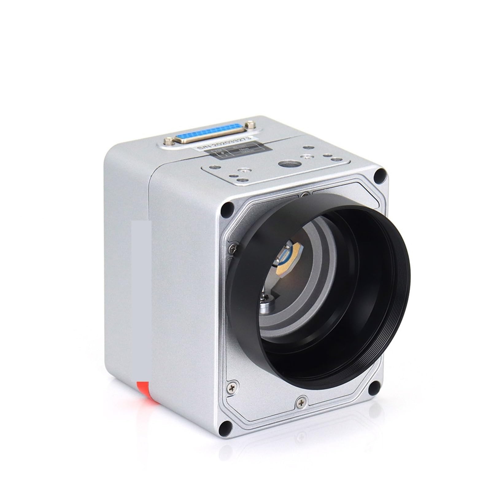


4. Setup and Installation
Proper installation and connection are critical for the optimal performance and longevity of your galvo head.
4.1. Power Supply Connection:
Connect the appropriate power supply to the galvo head. Ensure that the voltage and polarity match the device's requirements to prevent damage.
4.2. Signal Wiring:
Refer to the detailed wiring diagram below for connecting the control signals from your laser system to the galvo head's DB25 connector.

- Pins 1-2: CLOCK- and CLOCK+ (Typically Blue and white / Orange white wires)
- Pins 3-4: SYNC- and SYNC+ (Typically Orange white / Green white wires)
- Pins 5-6: CHAN1- and CHAN1+ (Typically Brown / Green wires)
- Pins 7-8: CHAN2- and CHAN2+ (Wire colors may vary, refer to your cable documentation)
- Pins 9-10: +15V Power (Typically Red wire)
- Pins 11-12: COM (Common Ground, Typically Black and Brown wires)
- Pins 13-14: -15V Power (Typically Blue wire)
Ensure all connections are secure and correctly polarized to prevent signal loss, electrical short circuits, or damage to the unit.
4.3. Optical Alignment:
The galvo head requires precise optical alignment with your laser source. Consult your specific laser system's documentation for detailed alignment procedures. Incorrect alignment can lead to poor scanning quality or reduced laser power at the workpiece.
5. Operating Instructions
Once the galvo head is properly installed and aligned, it is ready for operation through your laser control software.
- Power On: Turn on the power supply for the galvo head.
- Software Initialization: Launch your laser marking or scanning software and ensure it recognizes the connected galvo system.
- Command Execution: Send control signals (e.g., XY deflection commands, marking patterns) to the galvo head via the connected interface.
- Monitoring and Adjustment: Continuously monitor the scanning performance and adjust parameters as needed through your control software to achieve desired results.
This model is specifically designed for 10.6um CO2 lasers. Verify that your laser source matches this wavelength for optimal performance and to prevent damage.
6. Maintenance
Regular and proper maintenance will ensure the longevity and consistent performance of your galvo head.
- Optical Cleaning: Keep all optical surfaces (mirrors, lenses) clean. Use only approved optical cleaning solutions and lint-free wipes to avoid scratching or damaging the coatings.
- Connection Checks: Periodically inspect all electrical connections for tightness, signs of corrosion, or wear. Re-secure any loose connections.
- Environmental Control: Avoid exposing the device to excessive dust, moisture, high humidity, or extreme temperatures. Operate within the recommended environmental specifications.
- No Disassembly: Do not attempt to disassemble the galvo head beyond routine external cleaning. Internal components are sensitive and user disassembly may void the warranty and cause irreparable damage.
7. Troubleshooting
If you encounter issues during operation, refer to the following common problems and their potential solutions:
7.1. No Scanning Movement:
- Power Supply: Check all power supply connections and ensure the unit is receiving the correct voltage.
- Signal Cables: Verify that all signal cables are securely connected according to the wiring diagram (Figure 4).
- Control Software: Confirm that your control software is active and sending valid commands to the galvo head.
7.2. Inaccurate Scanning / Drift:
- Mounting Stability: Ensure the galvo head is securely mounted and free from any vibrations or external disturbances.
- Optical Path: Check for any obstructions or contamination in the optical path that might interfere with the laser beam.
- Input Signals: Verify that the input signals from your control system are stable and within the specified parameters.
- Warm-up Time: Allow the unit a few minutes to warm up after powering on, as some drift can occur during initial stabilization.
7.3. Laser Beam Not Visible (for models with red light):
- Note: This specific model (10.6um CO2, No Red Light) does not include a red light focusing feature. Therefore, this troubleshooting step is not applicable.
8. Specifications
| Feature | Specification |
|---|---|
| Model Number | RC1001 |
| Wavelength | 10.6um (CO2 Laser) |
| Aperture | 10mm |
| Item Weight | 3.53 ounces (approx. 100g) |
| Package Dimensions | 1.18 x 0.79 x 0.39 inches |
| Manufacturer | QXCIVR |
| Assembly Required | No (installation and integration required) |
9. Warranty and Support
For specific warranty information, technical assistance, or support, please contact your vendor or the manufacturer, QXCIVR. It is recommended to retain your purchase receipt as proof of purchase for any warranty claims.