1. Introduction
This manual provides essential information for the safe and effective operation, setup, and maintenance of the QXCIVR SG2206 355nm UV Lasering Scanning Galvo Head. Please read this manual thoroughly before using the device to ensure proper functionality and to prevent damage or injury.
2. Safety Information
WARNING: This device involves laser technology. Improper use can result in serious injury, including eye damage and skin burns. Always follow safety guidelines.
- Always wear appropriate laser safety eyewear when operating or near the device.
- Ensure the work area is properly enclosed and marked with laser warning signs.
- Never look directly into the laser beam or its reflections.
- Disconnect power before performing any maintenance or adjustments.
- Only qualified personnel should operate and maintain this equipment.
- Keep the device away from flammable materials.
3. Product Overview
The QXCIVR SG2206 is a high-performance 355nm UV lasering scanning galvo head designed for precise laser deflection and two-dimensional localization applications. It features a 10mm input aperture and is engineered for stable and accurate operation.

Figure 3.1: Front view of the QXCIVR SG2206 355nm UV Lasering Scanning Galvo Head. This image shows the main unit with its protective lens housing and the input aperture.
Key Features:
- Good Linearity: Ensures high resolution and precise repetitive scanning.
- High Speed Scanning: Provides stable performance with minimal zero drift and strong anti-interference capabilities.
- Extensive Application: Suitable for various lasering deflection and two-dimensional localization tasks.
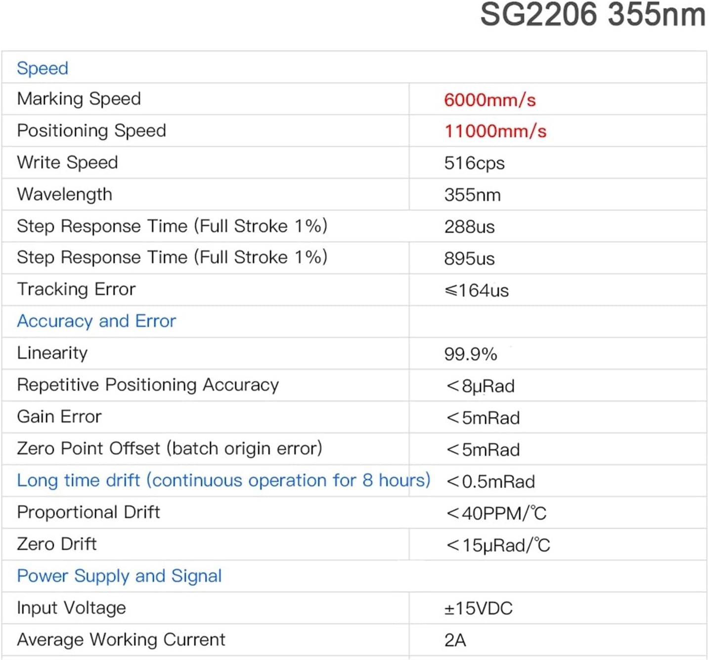
Figure 3.2: Close-up view of the internal scanning mirrors within the SG2206 Galvo Head. This image highlights the precision components responsible for laser beam deflection.
4. Specifications
The following tables detail the technical specifications and physical dimensions of the SG2206 Galvo Head.
Technical Specifications:

Figure 4.1: Detailed technical specifications for the SG2206 355nm UV Lasering Scanning Galvo Head, including speed, accuracy, and power supply requirements.
| Category | Parameter | Value |
|---|---|---|
| Speed | Marking Speed | 6000mm/s |
| Positioning Speed | 11000mm/s | |
| Write Speed | 516cps | |
| Step Response Time (Full Stroke 1%) | 288us | |
| Tracking Error | ≤164us | |
| Accuracy and Error | Linearity | 99.9% |
| Repetitive Positioning Accuracy | <8µRad | |
| Gain Error | <5mRad | |
| Zero Point Offset (batch origin error) | <5mRad | |
| Long time drift (continuous operation for 8 hours) | <0.5mRad | |
| General | Wavelength | 355nm |
| Aperture | 10mm | |
| Model Number | SG2206 | |
| Power Supply and Signal | Input Voltage | ±15VDC |
| Average Working Current | 2A | |
| Proportional Drift | <40PPM/°C | |
| Zero Drift | <15µRad/°C |
Physical Dimensions:

Figure 4.2: Dimensional drawing of the SG2206 Galvo Head, showing key measurements in millimeters for integration and mounting purposes.
- Package Dimensions: 1.18 x 0.79 x 0.39 inches
- Item Weight: 3.53 ounces
5. Setup
Proper setup is crucial for the performance and safety of the SG2206 Galvo Head. Follow these steps carefully.
5.1 Mounting
- Identify a stable, vibration-free surface for mounting the galvo head.
- Refer to the dimensional drawing (Figure 4.2) for mounting hole patterns and dimensions.
- Secure the galvo head using appropriate fasteners, ensuring it is level and firmly attached.
5.2 Electrical Connections
The SG2206 requires a ±15VDC power supply. Refer to the wiring diagram below for correct connections. Incorrect wiring can damage the device.
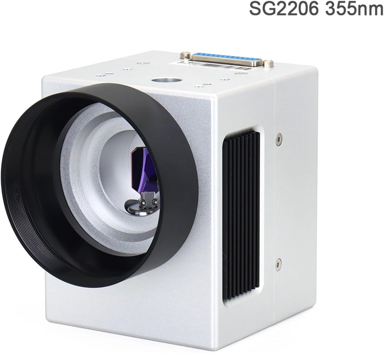
Figure 5.1: Detailed wiring diagram for the SG2206 Galvo Head, illustrating connections for clock, sync, channels, and power supply (±15V, GND, COM).
- Ensure the power supply is turned off before making any connections.
- Connect the power supply to the designated pins (+15V, -15V, GND) as shown in Figure 5.1.
- Connect the control signals (CLOCK+, CLOCK-, SYNC+, SYNC-, CHAN1+, CHAN1-, CHAN2+, CHAN2-) to your control system according to the diagram.
- Double-check all connections for polarity and secure fit.
6. Operating Instructions
Once the SG2206 Galvo Head is properly set up and connected, you can begin operation. Always ensure all safety precautions are in place.
- Verify that all electrical connections are secure and correct.
- Turn on the power supply to the galvo head.
- Initiate your laser control software or system.
- Load the desired marking or scanning pattern.
- Start the laser operation, monitoring the galvo head's movement and the laser output.
- Observe the system for any unusual behavior or errors. If detected, immediately shut down the system and refer to the troubleshooting section.
- After use, shut down the laser system and then turn off the power supply to the galvo head.
7. Maintenance
Regular maintenance helps ensure the longevity and optimal performance of your SG2206 Galvo Head.
- Cleaning: Periodically inspect the mirrors and optical surfaces for dust or debris. Use only approved optical cleaning solutions and lint-free wipes to clean these components. Avoid touching optical surfaces with bare hands.
- Environmental Control: Operate the galvo head in a clean, dry, and temperature-controlled environment to prevent condensation and contamination.
- Connection Check: Regularly inspect all electrical connections for looseness or corrosion.
- Calibration: If performance degrades or after significant environmental changes, recalibration may be necessary. Refer to your laser system's software documentation for calibration procedures.
8. Troubleshooting
This section provides guidance for common issues. For complex problems, contact technical support.
- No Movement/Response:
- Check power supply connections and ensure it is providing the correct voltage (±15VDC).
- Verify control signal connections from your laser system.
- Ensure the control software is running and configured correctly.
- Inaccurate Marking/Scanning:
- Check for any physical obstructions or debris on the mirrors.
- Perform a system calibration.
- Ensure the galvo head is securely mounted and not subject to vibrations.
- Overheating:
- Ensure adequate ventilation around the galvo head.
- Verify the ambient operating temperature is within specified limits.
- Reduce continuous operation time if necessary.
9. Warranty and Support
Specific warranty information for the QXCIVR SG2206 Galvo Head is not provided within this manual. Please refer to your purchase documentation or contact your vendor for details regarding warranty coverage and technical support.
For technical assistance or inquiries, please contact QXCIVR customer service or your authorized distributor.