1. Introduction
This manual provides comprehensive instructions for the installation, operation, and maintenance of the GYUQWC Motorbike Tacho Meter Instrument. This universal digital speedometer and odometer is designed for motorcycles, offering accurate display of speed, RPM, odometer readings, and other essential information. Please read this manual thoroughly before installation and use to ensure proper function and safety.

Figure 1: Front view of the Motorbike Tacho Meter Instrument.
2. Product Features
- Application: Designed for universal motorcycle use.
- Accurate Display: Digital odometer accurately displays speed and gear position.
- Essential Accessory: A practical and necessary instrument for motorcycle enthusiasts.
- Versatile: Widely used and highly practical for various motorcycle models.
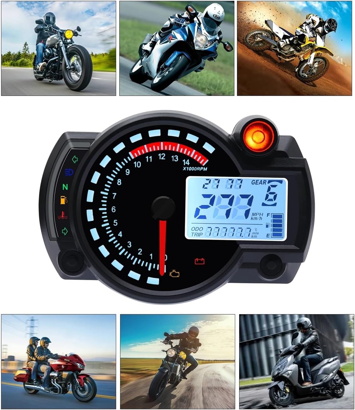
Figure 2: Examples of the instrument installed on different motorcycles, demonstrating its universal application.
3. Specifications
| Feature | Specification |
|---|---|
| Material | ABS plastic |
| Dimensions (L x W) | 140 x 99mm (5.5 x 3.9in) |
| Speed Sensor Cable Length | Approx. 125cm (49.2in) |
| Speed Sensor Size (L x D) | 40 x 12mm (1.6 x 0.5in) |
| Working Voltage | DC 12V |
| Speed Display Range | 0~299km/h (mile) |
| Odometer Display Range | 0~99999.9km (mile) |
| Trip Meter | Max. 999.9km |
| Gear Position Indicator | 1 to 6 |
| Package Weight | Approx. 422g |
4. Setup and Installation
Proper installation is crucial for the accurate operation of your new instrument. It is recommended that installation be performed by a qualified technician.
4.1 Package Contents
- 1 x Motorcycle Speedometer Unit
- 1 x Speed Sensor
- 2 x Magnets
- Mounting Brackets (if included with your specific variant)

Figure 3: Components included with the instrument, showing the main unit, speed sensor, and mounting brackets.
4.2 Mounting the Unit
- Select a suitable location on your motorcycle's dashboard or handlebars for optimal visibility and secure mounting.
- Use the provided mounting brackets and hardware to securely attach the speedometer unit. Ensure it is stable and does not obstruct your view or controls.
4.3 Wiring Connections
Connect the instrument's wiring harness to your motorcycle's electrical system according to the wiring diagram provided with your product. Typical connections include:
- Power (12V DC): Connect to a switched 12V power source.
- Ground: Connect to the motorcycle's chassis ground.
- Ignition Signal: For RPM readings.
- Speed Sensor Input: Connect the speed sensor cable.
- Turn Signals (Left/Right): For indicator lights.
- High Beam Indicator: For high beam light.
- Neutral Gear Indicator: For 'N' light.
- Fuel Level Sensor: For fuel gauge.
Note: Refer to your motorcycle's service manual for specific wiring color codes and locations.
4.4 Speed Sensor Installation
- Mount the speed sensor near a rotating part of the wheel (e.g., brake disc, wheel hub) where the magnets can pass by it.
- Attach the two magnets to the rotating part, ensuring they pass directly in front of the sensor with each rotation. The distance between the sensor and the magnets should be minimal for accurate readings.
- Secure the speed sensor cable away from moving parts and heat sources.
5. Operating Instructions
Once installed, the instrument will power on with the motorcycle's ignition. The display provides various readings and indicators.

Figure 4: Detailed view of the instrument's display with labeled indicators and readings.
5.1 Display Overview
- Speed: Displays current speed in km/h or mph.
- Tachometer (RPM): Analog needle and digital display for engine revolutions per minute.
- Odometer (ODO): Total distance traveled.
- Trip Meter (TRIP): Resettable distance for individual trips.
- Gear Position: Indicates current gear (1-6, N).
- Clock: Displays current time.
- Fuel Indicator: Shows approximate fuel level.
- Turn Signals: Left and Right turn indicators.
- High Beam Display: Indicator for high beam activation.
- N Gear Display Lamp: Indicator for Neutral gear.
- Oil Signal: Oil pressure warning light.
- Water Temperature: Engine coolant temperature indicator.
- Battery Under Voltage Lamp: Warning for low battery voltage.
- Engine Fault Light: Indicates a detected engine fault.
5.2 Button Functions
The instrument typically features one or more buttons for setting adjustments. Common functions include:
- Short Press: Toggle between Odometer and Trip Meter.
- Long Press (on Trip): Reset Trip Meter.
- Long Press (in ODO mode): Enter settings mode (e.g., unit conversion km/h to mph, clock adjustment, wheel circumference calibration).
Note: Specific button functions and setting procedures may vary slightly. Refer to the quick start guide included with your product for detailed instructions on calibration and settings.
6. Maintenance
To ensure the longevity and optimal performance of your instrument, follow these maintenance guidelines:
- Cleaning: Wipe the display and casing with a soft, damp cloth. Avoid abrasive cleaners or solvents that could damage the plastic.
- Connections: Periodically check all wiring connections to ensure they are secure and free from corrosion.
- Sensor: Inspect the speed sensor and magnets for any damage or misalignment. Ensure the sensor is clean and free of debris.
- Environmental Protection: While designed for motorcycle use, avoid prolonged exposure to extreme weather conditions when possible.
7. Troubleshooting
If you encounter issues with your instrument, refer to the following common problems and solutions:
| Problem | Possible Cause | Solution |
|---|---|---|
| No Power/Display Off | Loose wiring connection, blown fuse, faulty power source. | Check all power and ground connections. Inspect motorcycle fuses. Verify 12V power supply. |
| Incorrect Speed Reading | Speed sensor misalignment, damaged sensor/magnets, incorrect wheel circumference setting. | Ensure sensor and magnets are correctly aligned and clean. Check sensor cable for damage. Calibrate wheel circumference in settings. |
| RPM Not Displaying | Ignition signal wire not connected or faulty. | Verify the ignition signal wire connection. |
| Indicators Not Working | Loose connection for specific indicator, faulty bulb (if applicable), internal fault. | Check wiring for the specific indicator. If all connections are good, professional inspection may be needed. |
| Display Flickering/Erratic | Unstable power supply, loose internal connection, electrical interference. | Check motorcycle's charging system. Ensure all connections are tight. Try to isolate from other electrical components. |
If the problem persists after attempting these solutions, please contact customer support.
8. Warranty Information
Specific warranty details for this product are typically provided at the point of purchase or within separate documentation included with the product packaging. Please retain your proof of purchase for any warranty claims. Generally, warranties cover manufacturing defects under normal use conditions.
9. Customer Support
For technical assistance, troubleshooting beyond this manual, or warranty inquiries, please contact the manufacturer or your retailer. Provide your product model number (RX2N) and a detailed description of the issue when seeking support.
Manufacturer: GYUQWC
For further assistance, you may visit the product page on Amazon: Amazon Product Page