PowMr SunSmart SP5.2K-FBA-US
PowMr 5200W Hybrid Solar Inverter User Manual
Model: SunSmart SP5.2K-FBA-US
1. Introduction
This manual provides detailed instructions for the installation, operation, and maintenance of your PowMr 5200W Hybrid Solar Inverter. This inverter is designed to convert 48V DC power from solar panels and batteries into 110V/120V AC power for various applications. It features a built-in 100A MPPT charge controller and supports parallel operation for increased capacity.
Please read this manual thoroughly before installation and use to ensure proper function and safety.
2. Safety Instructions
- Installation must be performed by qualified personnel.
- Ensure all wiring complies with local and national electrical codes.
- Do not disassemble the inverter. There are no user-serviceable parts inside.
- Disconnect all power sources (PV, battery, AC input) before performing any maintenance or wiring.
- Wear appropriate personal protective equipment (PPE), including insulated gloves and eye protection.
- Avoid installing the inverter in direct sunlight, high humidity, or dusty environments.
- Ensure adequate ventilation around the inverter to prevent overheating.
- This inverter is designed for 48V battery systems. Do not connect to other voltage systems.
3. Product Overview and Features
The PowMr 5200W Hybrid Solar Inverter is an all-in-one solution for solar power systems, integrating a pure sine wave inverter, a 100A MPPT solar charge controller, and a battery charger function. It offers versatile power management for various applications.
Key Features:
- 5200W Pure Sine Wave Output: Provides stable and clean power suitable for sensitive electronics.
- 100A MPPT Solar Charge Controller: Maximizes power harvest from solar panels with a maximum PV input of 6000W and VOC up to 500V DC.
- 48V DC System Compatibility: Supports both lead-acid and lithium batteries.
- Parallel Operation: Up to 6 units can be connected in parallel for increased power output (up to 30000W in split phase).
- Multiple Output Configurations: Supports single-phase, split-phase (120/240V AC), and three-phase (120/208V AC) output.
- Battery-less Operation: Can power loads directly from PV and AC grid without a battery.
- Sectional Charging/Discharging: Allows users to set specific time periods for battery charging from mains or battery discharging, optimizing for peak-valley electricity tariffs.
- Intelligent Power Saving (ECO Mode): Reduces no-load loss by turning off output when load is below 50W for 5 minutes.
- Comprehensive Protections: Includes short circuit, over-current, over/under voltage, overload, and backfeed protection.
- Communication Interfaces: CAN, USB, and RS485 for monitoring and control.
Product Components:
Refer to the diagram below for an overview of the inverter's external components and connections.

Figure 3.1: Product Details and Ports. This image shows a detailed view of the inverter's various ports and features, including the dustproof cover, overload protector, ON/OFF switch, AC input/output ports, RS485-2 and USB communication ports, dry contact port, current sharing port, parallel communication port, PV port, cooling fan, battery port, function keys, and LCD screen.
4. Setup and Installation
Proper installation is crucial for the safe and efficient operation of the inverter. Follow these steps carefully.
4.1 Mounting the Inverter
- Choose a suitable location: indoors, well-ventilated, away from flammable materials, and protected from direct sunlight and moisture.
- Ensure the mounting surface can support the inverter's weight (approximately 30.8 lbs).
- Allow sufficient clearance around the inverter for proper airflow, especially around the cooling fans.
- Mount the inverter vertically using appropriate screws and anchors.
4.2 Wiring Connections
All wiring must be performed by a qualified electrician. Ensure all circuit breakers are OFF before making any connections.
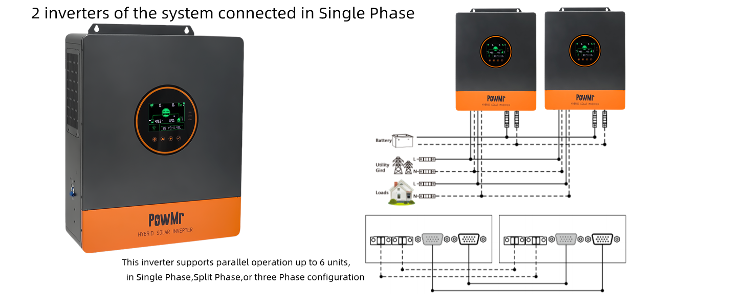
Figure 4.1: Basic Connection Diagram. This diagram illustrates the wiring connections for the PowMr 5200W Hybrid Solar Inverter, showing connections for solar panels, battery, AC input (mains power/generator), and AC output to home loads. It specifies wire types and circuit breaker requirements for each connection.
4.2.1 Battery Connection
- Connect the 48V battery bank to the inverter's battery terminals.
- Ensure correct polarity: positive to positive, negative to negative.
- Recommended battery type: Lead-acid or Lithium battery. Minimum starting voltage: 44V.
- Maximum charge current: 100A.
4.2.2 PV Input Connection
- Connect solar panels to the PV input terminals.
- Max PV Array Power: 6000W. Max PV Input VOC: 500V DC.
- MPPT Voltage Range: 120-450V DC. Starting voltage: >150V.
- Use appropriate PV cable (12-10AWG) and a 2P-25A circuit breaker.
- Ensure correct polarity.
4.2.3 AC Input Connection
- Connect the AC mains power or a generator to the AC input terminals.
- Input Voltage: 90-140Vac ±2%. Max AC Input Current: 63A.
- Frequency: 50/60Hz. Use 7AWG AC cable and a 2P-63A circuit breaker.
4.2.4 AC Output Connection
- Connect your home loads to the AC output terminals.
- Rated Output Power: 5200W. Rated Output Voltage: 120Vac (100/105/110V settable).
- Rated AC Frequency: 50/60Hz. Use 7AWG AC cable and a 2P-63A circuit breaker.
- Supports single-phase, split-phase (120/208V/240V AC), and three-phase output.
4.3 Parallel Operation (Optional)
The inverter supports parallel operation of up to 6 units for increased power capacity and multi-phase configurations.
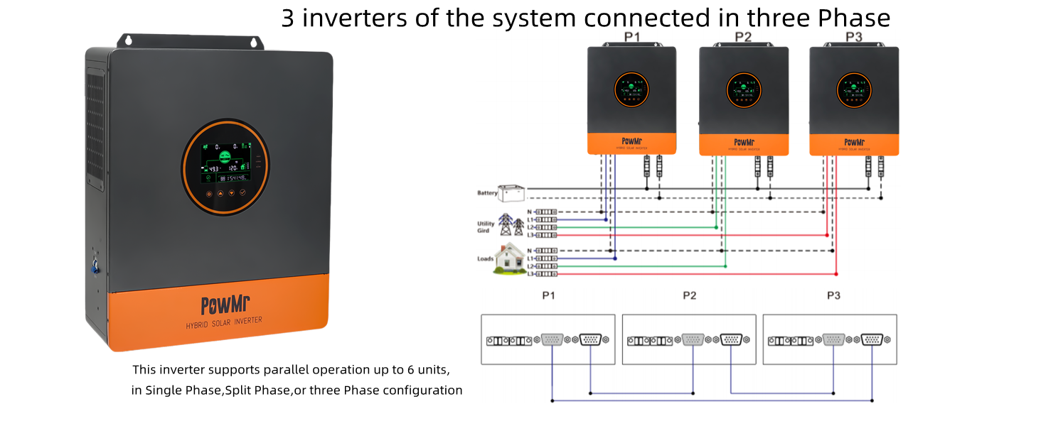
Figure 4.2: Parallel Connection for Split Phase (6 Inverters). This diagram shows how to connect six inverters in parallel to achieve a split-phase output of up to 30000W, detailing the battery, utility grid, and load connections for each phase (P1 and P2).

Figure 4.3: Parallel Connection for Single Phase (2 Inverters). This diagram illustrates connecting two inverters in parallel for a single-phase output of up to 10000W, showing the battery, utility grid, and load connections.

Figure 4.4: Parallel Connection for Three Phase (3 Inverters). This diagram shows how to connect three inverters in parallel to achieve a three-phase output of up to 15000W, detailing the battery, utility grid, and load connections for each phase (P1, P2, P3).
For detailed instructions on parallel communication wiring and configuration, refer to the dedicated section in the full product manual or contact PowMr support.
5. Operating Instructions
This section covers the basic operation, display interface, and configurable settings of your PowMr hybrid solar inverter.
5.1 Initial Power-Up
- After all wiring is complete and checked, switch on the battery circuit breaker.
- Switch on the PV array circuit breaker.
- Switch on the AC input circuit breaker (if connected to grid/generator).
- Press the ON/OFF rocker switch on the inverter to the "ON" position. The inverter will perform a self-test and then begin operation.
- Finally, switch on the AC output circuit breaker to power your loads.
5.2 LCD Display and Indicators
The inverter features a backlit LCD screen and LED indicators to display system status and parameters.

Figure 5.1: Smart LCD Screen Overview. This image highlights the various indicators and parameters displayed on the inverter's LCD screen, including solar power, mains power, PV parameters, battery parameters, load percentage, home load, real-time data, and total PV power generation.
Use the function keys below the display to navigate through menus and adjust settings.
5.3 Configurable Modes and Settings
5.3.1 Charging Modes
The inverter supports four charging modes:

Figure 5.2: Four Charging Modes. This diagram illustrates the four available charging modes: Solar First (PV priority), Mains First (Utility priority), Hybrid Charging (PV and Utility combined), and Only Solar (PV only).
- Solar First: Priority is given to PV charging. Mains charging starts only if PV power is insufficient.
- Mains First: Priority is given to mains charging. PV charging starts only if mains power fails.
- Hybrid Charging: Combines PV and mains power for charging. PV power is prioritized, and mains power supplements if PV is insufficient.
- Only Solar: Only PV power is used for charging; mains charging is not initiated.
5.3.2 Load Output Modes
The inverter offers four load output modes:

Figure 5.3: Four Load Output Modes. This diagram illustrates the four available load output modes: Solar First (PV and battery priority), Mains First (Inverter power supply only when mains fails), Inverter First (Mains power supply only when battery is under-voltage), and Hybrid Output (PV and utility together, with grid feedback if enabled).
- Solar First: PV and battery power the load. Switches to mains power if PV and battery are insufficient.
- Mains First: Inverter supplies power only when mains power fails. Otherwise, loads are powered by mains.
- Inverter First: Mains power supplies loads only when the battery is under-voltage. Otherwise, inverter powers loads.
- Hybrid Output: Loads are powered by PV and utility together. If grid connection is enabled, surplus PV energy can be fed back to the grid.
5.3.3 Sectional Charging/Discharging (Peak-Valley Tariff)
This function allows you to optimize energy usage based on electricity tariffs by setting specific time periods for charging from the grid or discharging the battery.
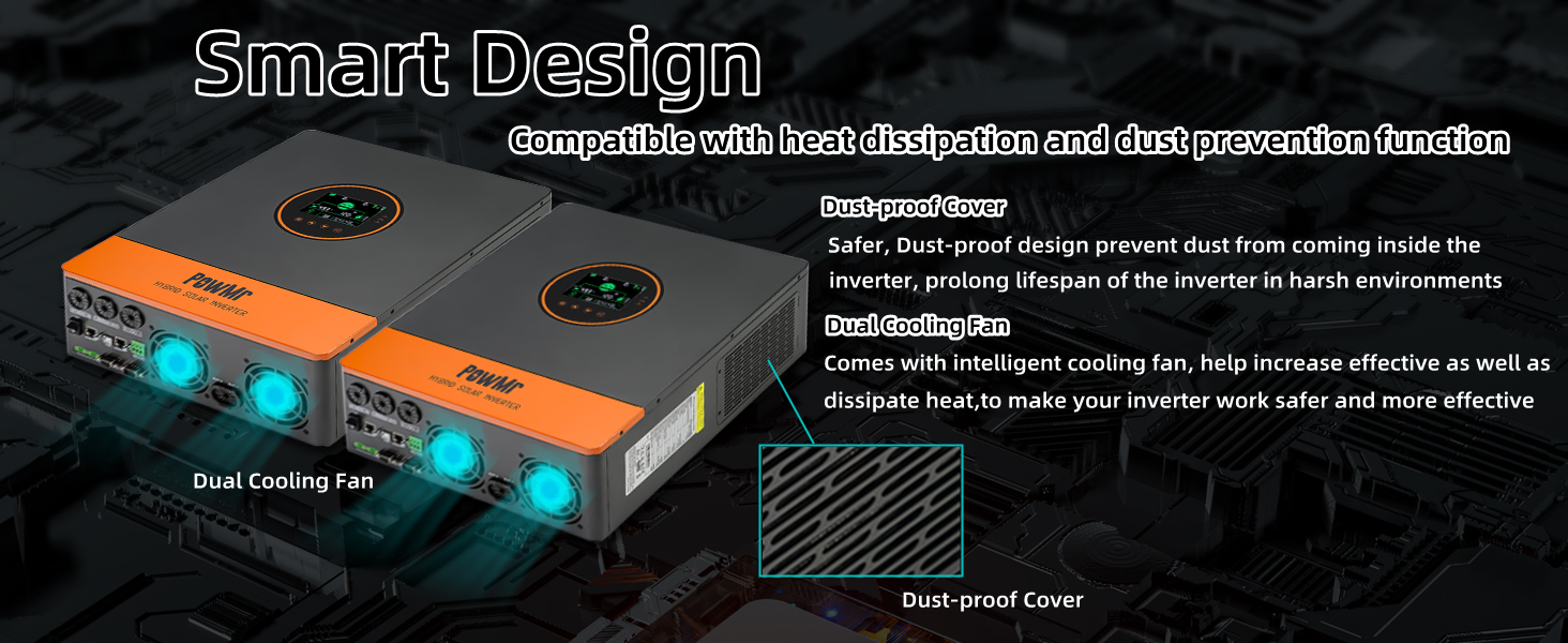
Figure 5.4: Peak-Valley Electricity Tariff Function. This image explains the sectional charging and discharging functions, allowing users to set three definable periods (00:00 to 23:59) for mains charging (BT1ST Mode) or battery discharge (AC1ST Mode) to align with local electricity tariff standards.
- BT1ST Mode (Sectional Charging Function): Set specific times for the inverter to charge batteries from the mains power.
- AC1ST Mode (Sectional Discharging Function): Set specific times for the inverter to discharge batteries to power loads.
- Users can define up to 3 periods between 00:00 and 23:59.
5.3.4 ECO Mode (Power Saving)
When ECO mode is enabled, if the load connected to the inverter is below 50W for 5 minutes, the inverter output will turn off to reduce idle power consumption. To resume output, press the ON/OFF switch to "OFF" and then back to "ON".

Figure 5.5: ECO Mode for Power Saving. This image illustrates the ECO mode feature, which reduces no-load loss by temporarily shutting down the inverter output when the load is below 50W for 5 minutes. It also shows how to reactivate the output.
5.3.5 Battery Type Compatibility
The inverter is compatible with various battery types, including FLD, SLD, AGM, GEL, and Lithium (LI). It also supports a user-defined setting.

Figure 5.6: Battery Type Compatibility. This image shows the inverter's compatibility with various 48V battery types, including FLD, SLD, AGM, GEL, and Lithium, along with a user-defined option. It also highlights the battery activation function for dormant lithium-ion batteries.
For lithium batteries, the inverter includes an activation function that can trigger dormant lithium-ion batteries via mains or photovoltaic power access.
6. Maintenance
Regular maintenance ensures the longevity and optimal performance of your inverter.
- Cleaning: Periodically clean the exterior of the inverter with a dry cloth. Ensure ventilation openings and cooling fans are free from dust and debris.
- Connections: Annually check all electrical connections for tightness and signs of corrosion. Loose connections can cause overheating and damage.
- Environment: Ensure the installation environment remains within specified temperature and humidity ranges.
- Battery Inspection: Follow the battery manufacturer's maintenance guidelines for your specific battery type.
- Firmware Updates: Check the PowMr website for any available firmware updates that may improve performance or add features.

Figure 6.1: Smart Design for Durability. This image highlights the inverter's smart design features, including dual intelligent cooling fans for effective heat dissipation and a dustproof cover to protect internal components, contributing to longer lifespan and safer operation.
7. Troubleshooting
This section provides solutions to common issues you might encounter. For problems not listed here, contact technical support.
| Problem | Possible Cause | Solution |
|---|---|---|
| Inverter does not power on. | Battery not connected or low voltage; ON/OFF switch off; circuit breaker tripped. | Check battery connections and voltage. Ensure ON/OFF switch is in "ON" position. Reset relevant circuit breakers. |
| No AC output. | Overload; battery low; inverter fault; AC output breaker off. | Reduce load. Check battery charge. Check inverter display for error codes. Ensure AC output breaker is on. |
| PV charging not active. | Insufficient solar input; PV voltage too low/high; PV circuit breaker off. | Check solar panel connections and ensure adequate sunlight. Verify PV voltage is within MPPT range (120-450V DC). Check PV circuit breaker. |
| Inverter making unusual noises (e.g., popping). | Internal component issue; loose connection. | Immediately disconnect all power sources. Do not attempt to fix. Contact PowMr technical support. |
| ECO mode activates unexpectedly. | Load is below 50W for 5 minutes. | This is normal operation. To resume output, toggle the ON/OFF switch. If you wish to disable ECO mode, refer to the full manual for settings adjustment. |
8. Specifications
| Parameter | Value |
|---|---|
| Model Name | SunSmart SP5.2K-FBA-US |
| Rated Power | 5200W |
| Battery Voltage | 48V DC |
| AC Output Voltage | 110V/120V AC (settable 100/105/110V) |
| AC Output Frequency | 50/60Hz |
| Max PV Array Power | 6000W |
| MPPT PV Voltage Range | 120-450V DC |
| Max PV Input VOC | 500V DC |
| Max PV Charging Current | 100A |
| Max AC Charging Current | 63A |
| AC Input Voltage Range | 90-140Vac ±2% |
| Product Dimensions | 13.78 x 17.59 x 5.24 inches |
| Item Weight | 30.8 pounds |
| Communication | CAN, USB, RS485 |
| Parallel Support | Up to 6 units |
9. Warranty and Support
For warranty information, please refer to the documentation included with your purchase or visit the official PowMr website. PowMr offers technical support for their products.
If you encounter issues not covered in this manual or require further assistance, please contact PowMr customer service. Have your model number (SunSmart SP5.2K-FBA-US) and purchase details ready.
PowMr Store: Visit the PowMr Store on Amazon