1. Introduction
This manual provides detailed instructions for the installation, operation, and maintenance of the FCNGEVBH LC908 PID Digital Temperature Controller. This device is designed for precise temperature regulation in industrial applications, featuring a 0-10V analog output and two configurable alarms. Please read this manual thoroughly before installation and operation to ensure correct usage and optimal performance.
2. Safety Information
Observe the following safety precautions to prevent personal injury or damage to the device:
- Ensure all power is disconnected before installation, wiring, or maintenance.
- Installation and wiring should only be performed by qualified personnel.
- Verify that the power supply voltage matches the specifications of the controller.
- Do not expose the device to moisture, extreme temperatures, or corrosive environments.
- Avoid touching internal components when the device is powered.
- Ensure proper grounding to prevent electrical shock.
3. Product Features
The FCNGEVBH LC908 PID Digital Temperature Controller offers a range of features for robust temperature control:
- Universal Input: Supports TC (Thermocouple) and RTD (Resistance Temperature Detector) inputs, as well as other analog universal inputs.
- LCD Display: Features a segment LCD display with high brightness backlight for clear readability and wide viewing angles.
- High Accuracy: Achieves an accuracy of 0.2% Full Scale (F.S.).
- Multiple Outputs: Includes measurement display, control output (0-10V analog), alarm output (up to 2 alarms), and RS485 communication.
- Control Modes: Supports manual and automatic control switching.
- Status Indicator: Provides clear indication of working status.
- Compact Design: Standard 96x96mm panel size for easy integration.
4. Specifications
| Parameter | Value |
|---|---|
| Model Number | LC908 |
| Input Type | TC/RTD, Analog Universal Input (e.g., 0-10V) |
| Output Type | 0-10V (Analog Control), Relay, SSR, 4-20mA (Configurable options) |
| Alarm Output | Maximum 2 Alarms (Configurable) |
| Communication | RS485 (Modbus compatible, configurable) |
| Accuracy | 0.2% F.S. |
| Sampling Time | 0.5 seconds |
| Power Supply | 85~265VAC, 50~60Hz |
| Panel Size | 96 x 96 mm |
| Operating Environment | Humidity < 85% RH (non-condensing) |
| Display Type | Digital LCD |
| Item Weight | 1.76 ounces (approximately 50 grams) |
| Package Dimensions | 1.18 x 0.79 x 0.39 inches (approximately 3 x 2 x 1 cm) |
5. Installation
The LC908 controller is designed for embedded panel mounting. Follow these steps for proper installation:
- Panel Cutout: Create a square cutout in your control panel with dimensions appropriate for a 96x96mm device. Refer to the product's physical dimensions for precise cutout requirements.
- Insert Controller: Carefully insert the controller into the cutout from the front of the panel.
- Secure Device: Use the provided mounting brackets to secure the controller firmly in place from the rear of the panel. Ensure it is flush with the panel surface.
- Environmental Considerations: Install the controller in an area free from excessive vibration, dust, moisture, and direct heat sources. Ensure adequate ventilation around the unit.
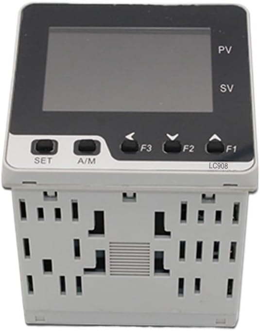
Figure 5.1: Front view of the LC908 controller, showing the LCD display and control buttons.

Figure 5.2: Angled view of the LC908 controller, illustrating its compact form factor suitable for panel mounting.
6. Wiring Diagram
Refer to the wiring diagram on the side of the unit and the detailed instructions below for correct electrical connections. Always ensure power is OFF before making any connections.
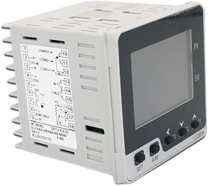
Figure 6.1: Side view of the LC908 controller displaying the terminal block and wiring diagram. This diagram indicates connections for power, input sensors, and output signals.
6.1 Power Supply Connection
- Connect the main power supply (85-265VAC, 50/60Hz) to the designated power terminals (typically marked AC-L and AC-N or similar).
- Ensure proper grounding of the unit.
6.2 Input Sensor Connection (0-10V Input Model)
- For 0-10V analog input, connect the signal source to the input terminals labeled for 0-10V.
- Observe polarity for analog signals.
6.3 Output Connection (0-10V Out, 2 Alarms Model)
- 0-10V Control Output: Connect the control input of your heating/cooling device (e.g., SSR, valve actuator) to the 0-10V output terminals.
- Alarm Outputs: Connect external alarm devices (e.g., buzzers, indicator lights) to the alarm relay terminals (AL1, AL2). These are typically dry contacts.
6.4 RS485 Communication (If applicable)
- If your model includes RS485, connect the A and B data lines to the corresponding RS485 terminals on the controller.
- Ensure proper termination resistors are used in the RS485 network if required.
7. Operation
Once wired and powered on, the controller will display the Process Value (PV) and Set Value (SV) on its LCD screen. The front panel buttons allow for navigation and parameter adjustment.
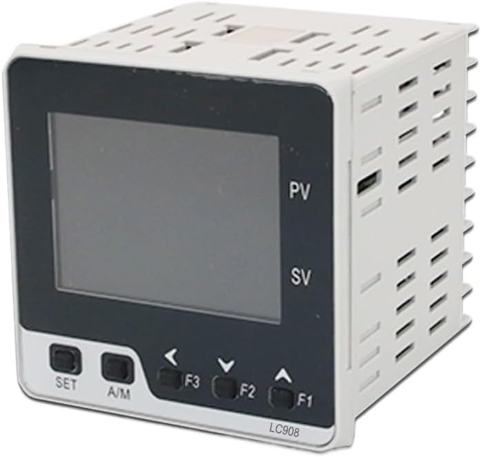
Figure 7.1: Close-up of the LC908 front panel, showing the SET, A/M, and navigation buttons (F1, F2, F3).
7.1 Front Panel Controls
- SET Button: Used to enter parameter setting mode and confirm selections.
- A/M Button: Toggles between Automatic and Manual control modes.
- F1 (Up Arrow): Increases parameter values or navigates up in menus.
- F2 (Down Arrow): Decreases parameter values or navigates down in menus.
- F3 (Left Arrow): Shifts cursor position during numerical input or navigates back.
7.2 Setting the Set Value (SV)
- In normal display mode, press the SET button briefly. The SV display will begin to flash.
- Use the F1 (Up) and F2 (Down) buttons to adjust the desired Set Value.
- Use the F3 (Left) button to move the cursor for faster adjustment of individual digits.
- Press SET again to confirm the new SV and exit the setting mode.
8. Configuration and Advanced Settings
Accessing advanced parameters typically involves pressing and holding the SET button for several seconds from the normal display mode. This will enter the parameter menu. Navigate through parameters using the F1 and F2 buttons, and adjust values using the same. Press SET to confirm and move to the next parameter or exit the menu.
Common configurable parameters include:
- Input Type: Select the type of sensor connected (e.g., K-type thermocouple, Pt100 RTD, 0-10V).
- Control Mode: PID, ON/OFF, etc.
- PID Parameters: Proportional band (P), Integral time (I), Derivative time (D) for fine-tuning control.
- Alarm Settings: Set alarm thresholds (high/low), hysteresis, and alarm types (deviation, absolute).
- Output Type: Confirm or change the control output type (e.g., 0-10V).
- RS485 Settings: Baud rate, parity, address for communication.
Refer to the full product manual (if provided separately by the manufacturer) for a complete list of parameters and their detailed descriptions.
9. Maintenance
The FCNGEVBH LC908 PID Digital Temperature Controller is designed for reliable operation with minimal maintenance. However, periodic checks can help ensure its longevity and accuracy:
- Cleaning: Gently wipe the display and front panel with a soft, dry cloth. Do not use abrasive cleaners or solvents.
- Connections: Periodically check all wiring connections for tightness and signs of corrosion. Ensure secure terminal connections.
- Environment: Verify that the operating environment remains within specified temperature and humidity ranges.
- Calibration: If accuracy issues are suspected, professional calibration may be required.
10. Troubleshooting
This section addresses common issues you might encounter with the LC908 controller.
| Problem | Possible Cause | Solution |
|---|---|---|
| No display/Power off | No power supply; Incorrect wiring; Blown fuse. | Check power connections and voltage. Verify wiring according to diagram. Check internal fuse (if accessible and user-serviceable). |
| PV display shows "HHHH" or "LLLL" | Sensor open circuit; Sensor short circuit; Sensor out of range; Incorrect input type setting. | Check sensor wiring and integrity. Ensure sensor type matches controller settings. Verify process value is within sensor's measurable range. |
| Output not responding | Incorrect output wiring; Output type mismatch; Control mode issue; PID parameters incorrect. | Verify output wiring. Ensure controller output type matches connected device. Check if in Manual mode (switch to Auto). Review PID parameters. |
| Temperature unstable/overshoot | PID parameters not tuned correctly; Sensor placement issue. | Perform PID auto-tuning or manually adjust P, I, D parameters. Ensure sensor is placed correctly to measure actual process temperature. |
| Alarms not activating | Alarm settings incorrect; Alarm output wiring issue. | Check alarm set points and hysteresis. Verify alarm output wiring. |
11. Warranty and Support
For specific warranty information, please refer to the documentation provided at the time of purchase or contact your vendor. For technical support, troubleshooting assistance beyond this manual, or inquiries regarding replacement parts, please contact FCNGEVBH customer service or your authorized distributor.
Keep your purchase receipt and product model number (LC908) readily available when contacting support.