1. Introduction
This manual provides detailed instructions for the installation, operation, and maintenance of the JUGJCKJL ADL400 Three Phase Energy Meter. The ADL400 is designed for accurate measurement of active energy in three-phase systems, featuring RS485 communication and zero export functionality. Please read this manual thoroughly before installation and operation to ensure correct usage and optimal performance.
This specific model supports direct connection for currents up to 80A.
2. Product Overview
The ADL400 energy meter features a clear LCD display and intuitive buttons for configuration and data viewing. Below is an overview of its main components and their functions.

Image 2.1: ADL400 Panel Overview. This image illustrates the front panel of the ADL400 energy meter, highlighting key components. From left to right, top to bottom: 'Brand' (JUGJCKJL), 'Terminal Cover' (top section), 'LCD Display' (main screen), 'Pulse Output' (LED indicator), 'SET Button' (left button), 'Left Button' (middle button), 'Enter Button' (right button), and 'Model' (ADL400).
Front Panel Components:
- LCD Display: Shows real-time energy data, voltage, current, power, and other parameters.
- SET Button: Used to enter setup menus or confirm selections.
- Left Button: Navigates through menu options or decreases values.
- Enter Button: Confirms selections or advances to the next parameter.
- Pulse Output: An LED indicator that flashes to indicate active energy consumption.
- Terminal Cover: Protects the wiring terminals at the top and bottom of the device.
3. Technical Parameters
The ADL400 energy meter is designed with the following technical specifications:
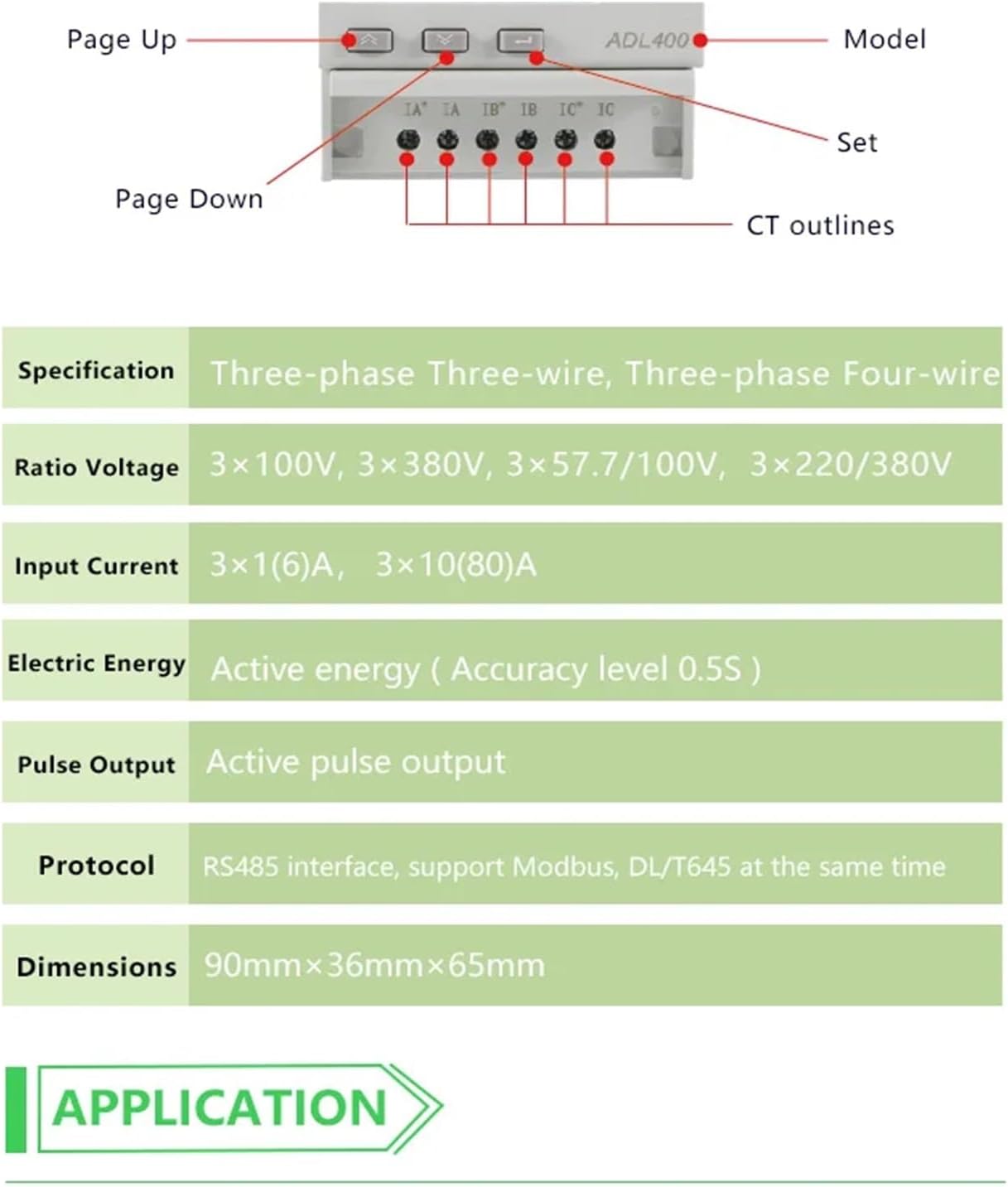
Image 3.1: ADL400 Technical Parameters and Wiring Diagram. This image displays a table of technical specifications for the ADL400 meter, including its supported wiring types, voltage ranges, current inputs, energy accuracy, pulse output, and communication protocols. It also shows a simplified wiring diagram for voltage inputs (UA, UB, UC, UN) and RS485 communication (21, 22, 17, 18), as well as current transformer (CT) outlines (IA, IB, IC).
| Parameter | Value |
|---|---|
| Specification | Three-phase Three-wire, Three-phase Four-wire |
| Ratio Voltage | 3×100V, 3×380V, 3×57.7/100V, 3×220/380V |
| Input Current | 3×10(80)A (Direct Connect) |
| Electric Energy | Active energy (Accuracy level 0.5S) |
| Pulse Output | Active pulse output |
| Protocol | RS485 interface, support Modbus, DL/T645 |
| Dimensions | 90mm × 36mm × 65mm (L×W×H) |
4. Setup and Installation
The ADL400 is designed for DIN rail mounting. Ensure all power is disconnected before proceeding with installation.

Image 4.1: ADL400 Dimensions. This image provides the physical dimensions of the ADL400 energy meter, showing a width of 72mm and a height of 90mm for the main body, with a depth of 65mm. These dimensions are crucial for proper DIN rail mounting and panel integration.
4.1 Mounting
- Mount the ADL400 onto a standard 35mm DIN rail in an electrical cabinet or distribution box.
- Ensure adequate ventilation around the meter to prevent overheating.
4.2 Wiring (80A Directly Connect)
Refer to the wiring diagram (Image 3.1) for terminal connections. Use appropriate wire gauges for the expected current load.
- Voltage Inputs (UA, UB, UC, UN): Connect the three-phase voltage lines (L1, L2, L3) and the neutral line (N) to the corresponding terminals (UA, UB, UC, UN) at the top of the meter.
- Current Inputs (IA, IB, IC): For direct connect models, connect the load current lines directly through the meter's current terminals (IA, IB, IC) at the bottom. Ensure correct polarity.
- RS485 Communication (21, 22, 17, 18): Connect the RS485 A and B lines to terminals 21 and 22 respectively. Terminals 17 and 18 are typically for auxiliary power or other communication lines if applicable.
- Pulse Output: If using the pulse output, connect it to the desired monitoring system.
Warning: Incorrect wiring can cause damage to the meter and connected equipment, and poses a risk of electric shock. Always consult a qualified electrician for installation.
5. Operating Instructions
Once installed and powered, the ADL400 will automatically begin measuring energy. The LCD display shows various parameters, which can be navigated using the front panel buttons.

Image 5.1: ADL400 Display. This image shows the ADL400 energy meter's LCD display, indicating 'EP' (Energy Positive) and a reading of '184 kWh' for total active energy. Below that, '30.00' is displayed, which could represent instantaneous power or another parameter. The display also shows '400 imp/kWh', '3x220/380V 50Hz', and '3x10(80)A', indicating the meter's pulse constant, voltage rating, frequency, and current rating.
5.1 Display Navigation
- Left Button (▲): Typically used for 'Page Up' or increasing values in settings.
- Middle Button (▼): Typically used for 'Page Down' or decreasing values in settings.
- Right Button (↵): Used to enter menus, confirm selections, or cycle through display pages.
Press the Right Button to cycle through different display screens, which may include:
- Total Active Energy (kWh)
- Instantaneous Voltage (V) per phase
- Instantaneous Current (A) per phase
- Instantaneous Active Power (kW) per phase and total
- Power Factor
- Frequency (Hz)
- RS485 Communication Address
5.2 Configuration (SET Button)
Press and hold the SET button to enter the configuration menu. Use the Left and Middle buttons to navigate and the Enter button to select or confirm. Refer to the detailed communication protocol documentation for advanced RS485 settings.
6. Maintenance
The ADL400 energy meter is designed for long-term, maintenance-free operation. However, periodic checks are recommended:
- Cleaning: Use a soft, dry cloth to clean the meter's exterior. Do not use abrasive cleaners or solvents.
- Connection Check: Periodically inspect wiring connections to ensure they are secure and free from corrosion. Ensure power is off before checking connections.
- Environmental Conditions: Ensure the operating environment remains within specified temperature and humidity ranges.
7. Troubleshooting
If you encounter issues with your ADL400 meter, refer to the following common problems and solutions:
- No Display:
- Check if the power supply is connected correctly and is within the specified voltage range.
- Verify that the circuit breaker or fuse supplying power to the meter is not tripped or blown.
- Incorrect Readings:
- Ensure all wiring, especially current and voltage connections, are correct and secure. Incorrect polarity can lead to inaccurate readings.
- Verify the meter's configuration settings match the system parameters (e.g., voltage ratio).
- RS485 Communication Failure:
- Check RS485 wiring (A and B lines) for correct polarity and secure connections.
- Verify the meter's RS485 address and baud rate settings match the communication master.
- Ensure termination resistors are correctly applied if necessary in the RS485 network.
- Pulse Output Not Functioning:
- Confirm that the meter is measuring active energy.
- Check the connection to the pulse receiving device.
If problems persist, contact JUGJCKJL customer support or a qualified technician.
8. Specifications Summary
| Parameter | Value |
|---|---|
| Model | ADL400 |
| ASIN | B0F25JDTFQ |
| Manufacturer | JUGJCKJL |
| Wiring Type | Three-phase Three-wire, Three-phase Four-wire |
| Voltage Range | 3×100V, 3×380V, 3×57.7/100V, 3×220/380V |
| Input Current | 3×10(80)A (Direct Connect) |
| Energy Accuracy | Active energy (Accuracy level 0.5S) |
| Communication | RS485 (Modbus, DL/T645) |
| Pulse Output | Active pulse output |
| Dimensions (L×W×H) | 90mm × 36mm × 65mm |
| Item Weight | 7.1 ounces |
| Package Dimensions | 1.18 x 0.79 x 0.39 inches |
9. Warranty and Support
For warranty information and technical support, please refer to the product packaging or contact JUGJCKJL customer service directly. Keep your purchase receipt as proof of purchase for warranty claims.