1. Introduction and Safety Information
This manual provides essential information for the safe and effective operation of your NJTY T58A Digital Multimeter. Please read this manual thoroughly before use and retain it for future reference.
1.1 General Safety Warnings
- Always adhere to local and national safety codes.
- Do not use the multimeter if it appears damaged or if the insulation on the test leads is compromised.
- Ensure the correct function and range are selected before making measurements.
- Do not exceed the maximum input values for any range.
- Exercise extreme caution when working with voltages above 60V DC or 30V AC RMS, as these pose a shock hazard.
- Keep fingers behind the finger guards on the test probes during use.
- Replace the battery immediately when the low battery indicator appears to ensure accurate readings.
2. Product Overview
The NJTY T58A is a handheld digital multimeter designed for accurate measurement of AC/DC voltage, AC/DC current, frequency, resistance, capacitance, and diodes. It features a large 60000 counts LCD digital display with backlight and a built-in flashlight for enhanced visibility.
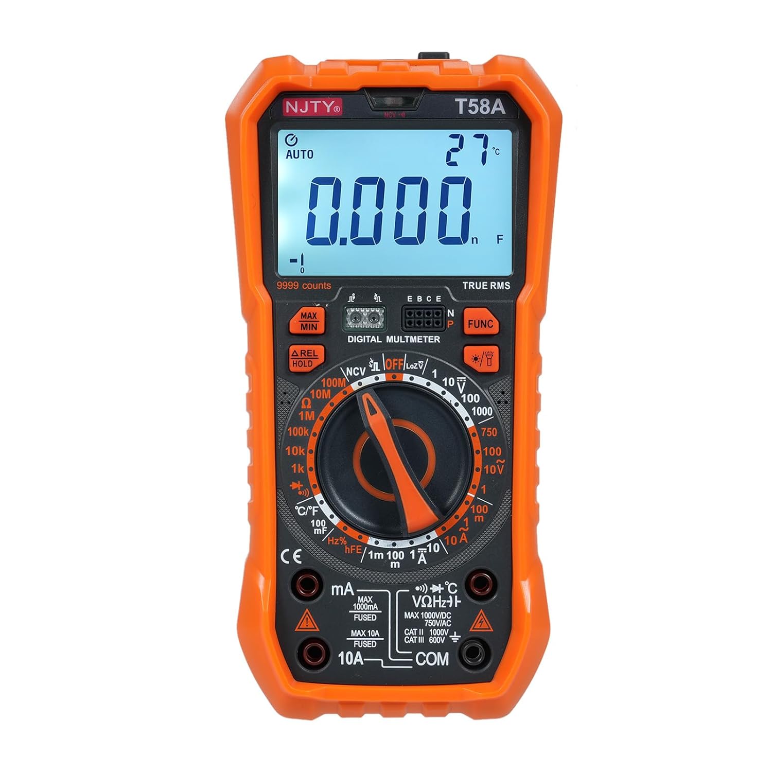
Figure 2.1: Front view of the NJTY T58A Digital Multimeter, showing the display, rotary switch, and input jacks.
2.1 Components and Display

Figure 2.2: Labeled diagram identifying key components of the NJTY T58A Multimeter.
- LED Display: Large 60000 counts LCD for clear readings.
- Illumination: Built-in flashlight for working in low-light conditions.
- NCV Sensing Area: For non-contact voltage detection.
- NCV and Buzzer Indicator Light: Visual and audible alerts for NCV.
- Maximum and Minimum Switching: Button to toggle between MAX/MIN readings.
- Data Hold/Relative Value Measurement: Button for freezing display or relative measurements.
- Functions Switch Button: For selecting specific sub-functions within a rotary switch position.
- Lighting/Backlight Button: To activate the display backlight and flashlight.
- Gear Rotary Switch: Main selector for measurement functions.
- Input Sockets: mA, 10A, VΩHz°C, and COM for test lead connections.
- Transistor Jack: For hFE measurements (T58A only).
3. Setup
3.1 Battery Installation
The NJTY T58A Multimeter requires 3 x 1.5V AAA batteries (not included). To install or replace batteries:
- Ensure the multimeter is turned OFF and test leads are disconnected.
- Locate the battery compartment cover on the back of the unit.
- Use a screwdriver to remove the screw securing the cover.
- Insert the AAA batteries, observing correct polarity (+ and -).
- Replace the battery compartment cover and secure it with the screw.
3.2 Test Lead Connection
Connect the test leads to the appropriate input jacks for the desired measurement:
- For most measurements (Voltage, Resistance, Capacitance, Frequency, Diode, Temperature): Insert the red test lead into the VΩHz°C jack and the black test lead into the COM jack.
- For Current measurements (up to 600mA): Insert the red test lead into the mA jack and the black test lead into the COM jack.
- For High Current measurements (up to 10A): Insert the red test lead into the 10A jack and the black test lead into the COM jack.

Figure 3.1: Back view of the multimeter showing the integrated stand and test lead storage. Test leads are connected to the appropriate input jacks.
4. Operating Instructions
To operate the multimeter, rotate the gear rotary switch to the desired function. Use the 'FUNC' button to select specific sub-functions if available within a range.
4.1 AC/DC Voltage Measurement
- Connect the red test lead to the VΩHz°C jack and the black test lead to the COM jack.
- Rotate the rotary switch to the V~ (AC Voltage) or V- (DC Voltage) position.
- Touch the test probes to the circuit points where voltage is to be measured.
- Read the voltage value on the display.
4.2 AC/DC Current Measurement
- For mA: Connect the red test lead to the mA jack and the black test lead to the COM jack.
- For 10A: Connect the red test lead to the 10A jack and the black test lead to the COM jack.
- Rotate the rotary switch to the A~ (AC Current) or A- (DC Current) position.
- Open the circuit where current is to be measured and connect the multimeter in series.
- Read the current value on the display.
4.3 Resistance Measurement
- Connect the red test lead to the VΩHz°C jack and the black test lead to the COM jack.
- Rotate the rotary switch to the Ω position.
- Ensure the circuit is de-energized before measuring resistance.
- Touch the test probes across the component to be measured.
- Read the resistance value on the display.
4.4 Capacitance Measurement
- Connect the red test lead to the VΩHz°C jack and the black test lead to the COM jack.
- Rotate the rotary switch to the capacitance (F) position.
- Ensure the capacitor is fully discharged before measurement to prevent damage to the meter.
- Touch the test probes across the capacitor terminals.
- Read the capacitance value on the display.
4.5 NCV (Non-Contact Voltage) Test
The NCV function allows for detection of AC voltage without direct contact with conductors.
- Rotate the rotary switch to the NCV position.
- Place the top of the meter (NCV sensing area) close to the conductor.
- If AC voltage is detected, the corresponding signal strength indicator (low-yellow, high-red) will light up, and the buzzer will emit different frequency alarms.

Figure 4.1: The multimeter detecting AC voltage using the NCV function near an electrical outlet.
4.6 Diode and Continuity Test
- Connect the red test lead to the VΩHz°C jack and the black test lead to the COM jack.
- Rotate the rotary switch to the diode/continuity position. Use the 'FUNC' button to toggle between diode and continuity.
- For Diode Test: Touch the red probe to the anode and the black probe to the cathode of the diode. The forward voltage drop will be displayed. Reverse the probes; an open circuit reading indicates a good diode.
- For Continuity Test: Touch the probes to the two points to be tested. A continuous beep indicates continuity (low resistance).
4.7 Frequency Measurement
- Connect the red test lead to the VΩHz°C jack and the black test lead to the COM jack.
- Rotate the rotary switch to the Hz position.
- Touch the test probes to the circuit where frequency is to be measured.
- Read the frequency value on the display.
4.8 Temperature Measurement (with Thermocouple)
- Connect the thermocouple to the VΩHz°C and COM jacks, observing polarity.
- Rotate the rotary switch to the °C/°F position.
- Place the thermocouple tip on or near the object whose temperature is to be measured.
- Read the temperature value on the display.
4.9 Transistor (hFE) Measurement (T58A only)
- Rotate the rotary switch to the hFE position.
- Insert the transistor leads into the corresponding E, B, C holes in the Transistor Jack, ensuring correct NPN or PNP type.
- Read the hFE value on the display.
5. Features
5.1 Automatic Shutdown
The multimeter is equipped with an automatic power-off feature to conserve battery life. If there is no operation for approximately 15 minutes after power-on, the instrument will emit audible voice prompts and then automatically shut off, entering hibernation mode. Press any key to restart the device.

Figure 5.1: The multimeter illustrating the 15-minute automatic shutdown feature to save power.
5.2 Backlit Screen and Flashlight
The large LCD display features a backlight that automatically adjusts brightness when turned on, improving readability in various lighting conditions. A built-in flashlight illuminates the front area, assisting users in dark environments during work.

Figure 5.2: The multimeter with its backlit screen and flashlight activated, demonstrating enhanced visibility.
5.3 Integrated Support Stand
The multimeter includes a 90-degree arc design back bracket that functions as a support stand, allowing the device to be propped up for easier viewing during use. It also features an anti-fall and anti-shock thoughtful watch pen storage slot for the test leads.
6. Specifications
The following table outlines the key specifications for the NJTY T58A Digital Multimeter.

Figure 6.1: Detailed parameter comparison for T58A, T58B, and T58C models.
| Parameter | Specification (T58A) |
|---|---|
| Model | T58A |
| Material | ABS |
| Safety Rating | 600V CAT III and 1000V CAT.II |
| Pollution Grade | 2 |
| Height | Under 2000m |
| Working Temperature | 0-40℃ |
| Storage Temperature | -10~60℃ |
| Item Size | 187 x 95 x 55mm (7.36 x 3.74 x 2.16 inches) |
| Item Weight | 331g (11.67oz) |
| Display | 9999 Counts LCD |
| DC Voltage | 1V, 10V, 100V, 1000V |
| AC Voltage | 1V, 10V, 100V, 750V |
| DC Current | 1mA, 100mA, 1A, 10A |
| AC Current | 1mA, 100mA, 1A, 10A |
| Resistance | 1kΩ, 10kΩ, 100kΩ, 1MΩ, 10MΩ, 100MΩ |
| Capacitance | 1nF, 10nF, 100nF, 1μF, 10μF, 100μF |
| Frequency | 10Hz, 100Hz, 1kHz, 10kHz, 100kHz, 1MHz, 10MHz |
| Temperature | -55°C~1000°C / -67°F~1832°F |
| Power Supply | 3 * 1.5V AAA batteries (Not Included) |
7. Maintenance
7.1 Cleaning
To clean the multimeter, wipe the case with a damp cloth and a mild detergent. Do not use abrasives or solvents. Ensure the device is off and disconnected from any circuits before cleaning.
7.2 Battery Replacement
When the low battery indicator appears on the display, replace the batteries as described in Section 3.1. Using the multimeter with a low battery can lead to inaccurate readings.
7.3 Fuse Replacement
If the current measurement function fails, the fuse may need replacement. Refer to the specifications for the correct fuse type and rating. Fuse replacement should only be performed by qualified personnel.
8. Troubleshooting
If you encounter issues with your multimeter, refer to the following common problems and solutions:
- No Display: Check battery installation and ensure batteries are not depleted. Replace if necessary.
- Inaccurate Readings: Ensure the correct function and range are selected. Check battery level. Verify test lead connections.
- No Current Measurement: Check if the fuse is blown. Replace if needed (refer to Section 7.3). Ensure test leads are connected to the correct current input jacks (mA or 10A).
- NCV Not Detecting: Ensure the rotary switch is in the NCV position. The NCV function detects AC voltage; it will not respond to DC voltage.
9. Warranty and Support
For warranty information or technical support, please refer to the documentation provided at the point of purchase or contact your retailer. Keep your purchase receipt as proof of purchase.