1. Introduction
This manual provides essential information for the proper installation, operation, and maintenance of the EQBVZZRD ECN 413 2048 16S15-2K Absolute Taper Shaft Encoder. This device is designed for precise measurement of rotation speed, angle, acceleration, and length in various industrial and scientific applications. Please read this manual thoroughly before using the product to ensure safe and efficient operation.
2. Safety Information
Always observe the following safety precautions to prevent injury and damage to the equipment:
- Ensure all power is disconnected before installation or maintenance.
- Only qualified personnel should perform installation and wiring.
- Do not expose the encoder to excessive moisture, dust, or extreme temperatures.
- Verify correct wiring connections to prevent electrical damage.
- Avoid applying excessive force to the shaft or housing during installation.
3. Product Overview
The EQBVZZRD ECN 413 2048 16S15-2K is a robust absolute taper shaft encoder designed for high-precision feedback in control systems. Its compact design and stable performance make it suitable for diverse applications.
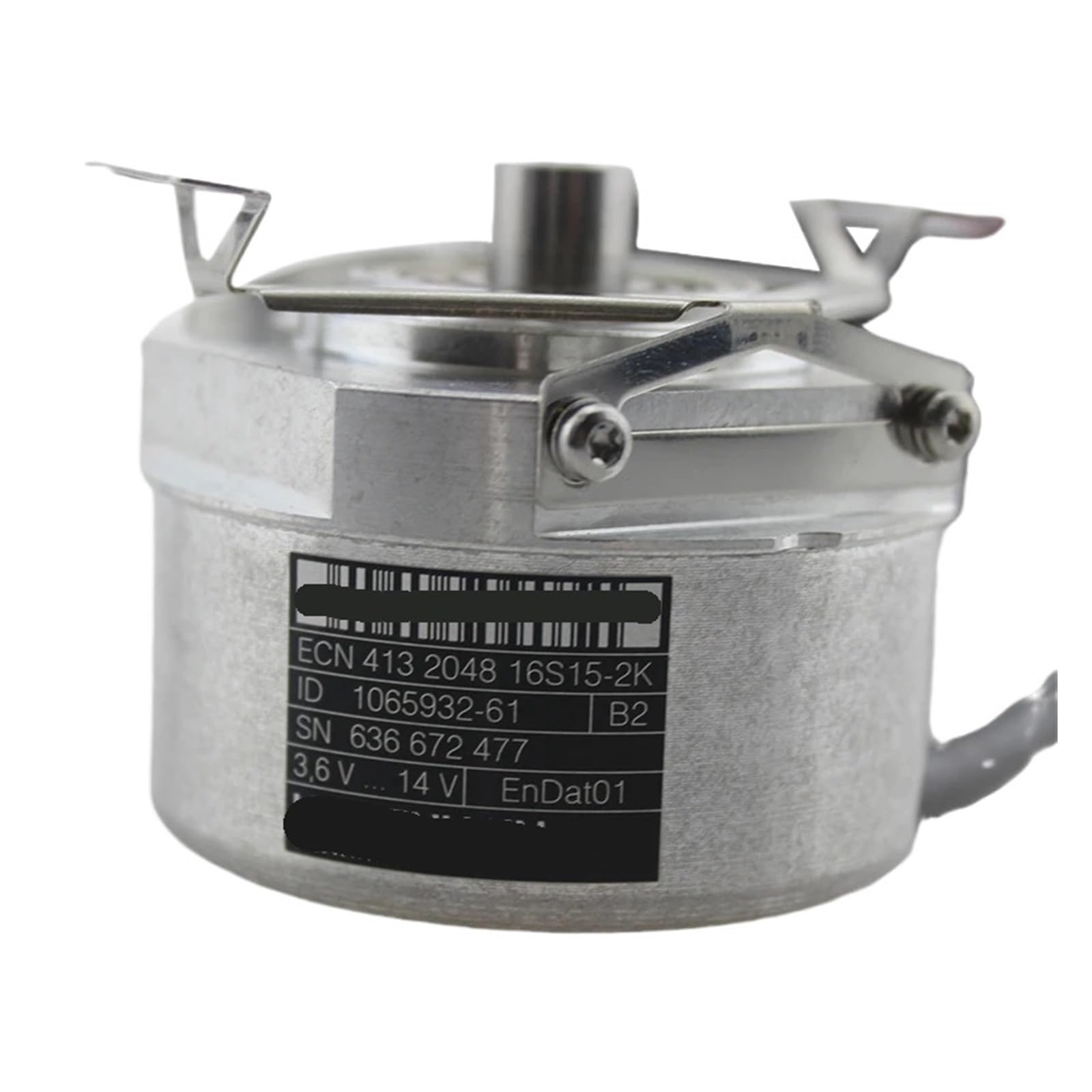
Figure 1: Top-down view of the EQBVZZRD ECN 413 2048 16S15-2K Absolute Taper Shaft Encoder, showing the central shaft and mounting brackets.

Figure 2: The encoder unit with its integrated connection cable and connector, ready for installation.
4. Specifications
| Specification | Value |
|---|---|
| Model Number | ECN 413 2048 16S15-2K |
| Brand | EQBVZZRD |
| Package Dimensions | 1.18 x 0.79 x 0.39 inches |
| Item Weight | 1.32 pounds |
| Manufacturer | EQBVZZRD |
| Assembly Required | No |
| Number of Pieces | 1 |
5. Setup and Installation
The ECN 413 2048 16S15-2K encoder is designed for easy installation due to its light weight and small size. Follow these general steps for proper setup:
- Mounting: Securely mount the encoder to the desired application point using appropriate fasteners. Ensure the taper shaft is correctly aligned with the rotating component it will measure.
- Shaft Connection: Carefully connect the encoder's taper shaft to the rotating mechanism. Avoid applying excessive radial or axial load to the shaft.
- Wiring: Connect the encoder's cable to your control system according to the wiring diagram provided with your specific system. Ensure all connections are secure and correctly polarized.
- Power On: Once all connections are verified, apply power to the system.
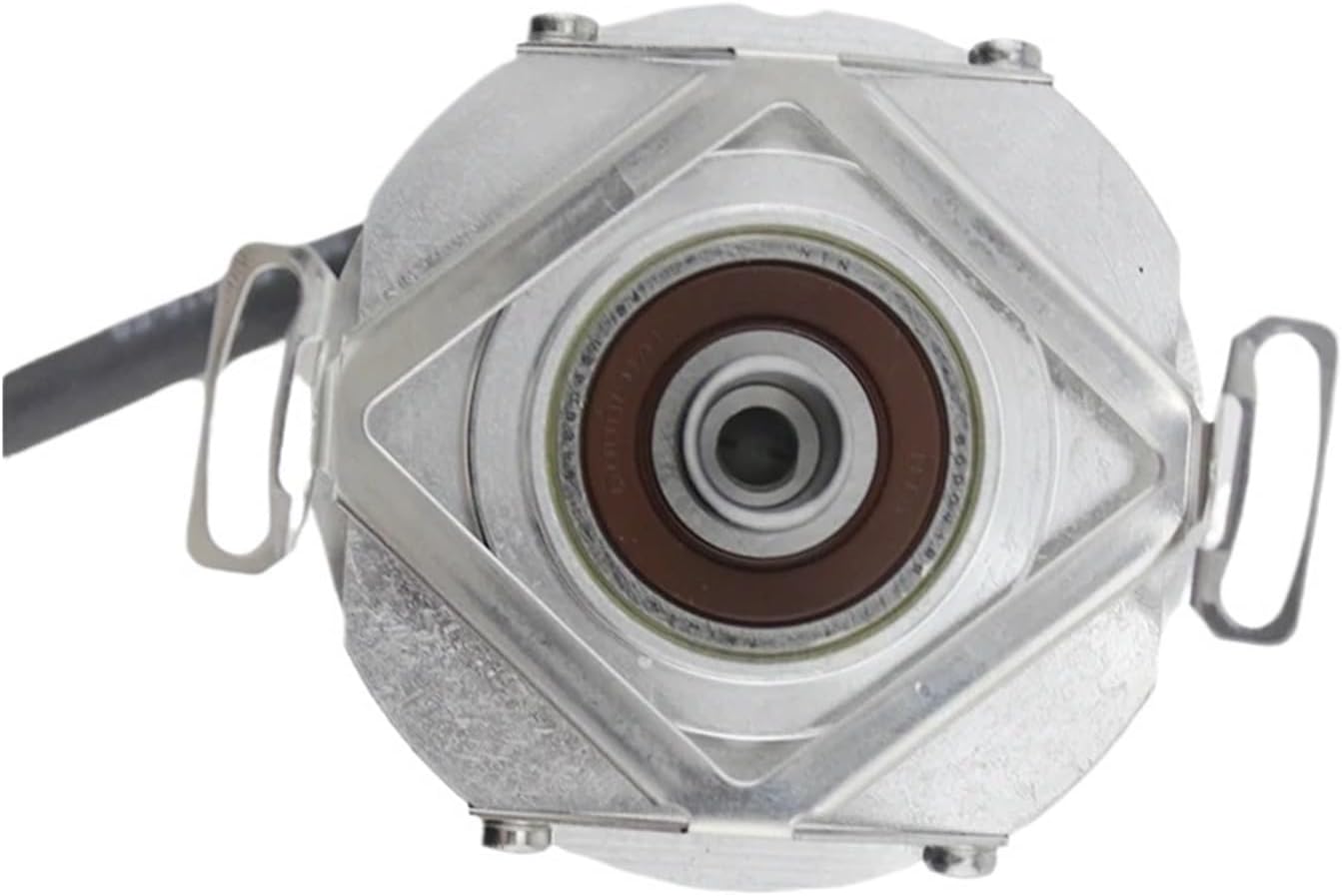
Figure 3: Close-up view of the encoder's taper shaft, which connects to the rotating element for measurement.

Figure 4: Bottom view of the encoder, illustrating the secure entry point for the shaft connection.
6. Operating Instructions
The ECN 413 2048 16S15-2K encoder provides precise feedback for various measurements:
- Rotation Speed: The encoder outputs signals proportional to the rotational speed of the connected shaft. This data can be processed by a control system to monitor and regulate speed.
- Angle: By tracking the encoder's output, the absolute angular position of the shaft can be determined.
- Acceleration: Changes in rotational speed over time can be calculated from the encoder's output to determine angular acceleration.
- Length: When integrated with a linear motion system (e.g., a measuring wheel), the encoder can be used to measure linear displacement and length.
This encoder is suitable for intelligent control in applications such as displacement measurement, steel cutting length control, height and weight scales, and student racing robots.

Figure 5: Side view of the encoder, highlighting the cable entry point for electrical connections.
7. Maintenance
The ECN 413 2048 16S15-2K encoder is designed for stable performance and requires minimal maintenance. However, regular checks can prolong its lifespan:
- Cleaning: Keep the encoder housing clean and free from dust, debris, and moisture. Use a soft, dry cloth for cleaning.
- Cable Inspection: Periodically inspect the connecting cable for any signs of wear, damage, or loose connections.
- Mounting Security: Ensure the encoder remains securely mounted and that the shaft connection is firm.
- Environmental Conditions: Operate the encoder within its specified environmental limits (temperature, humidity) to ensure optimal performance.
8. Troubleshooting
If you encounter issues with your encoder, consider the following common troubleshooting steps:
- No Output Signal:
- Check power supply to the encoder.
- Verify all wiring connections are correct and secure.
- Ensure the shaft is rotating and properly coupled.
- Inaccurate Readings:
- Check for mechanical play or slippage in the shaft coupling.
- Ensure the encoder is securely mounted and not vibrating excessively.
- Verify the control system's configuration matches the encoder's specifications.
- Intermittent Signal:
- Inspect the cable for damage or intermittent breaks.
- Check for electromagnetic interference (EMI) from nearby equipment. Use shielded cables if necessary.
If problems persist, contact technical support.
9. Warranty and Support
For warranty information or technical assistance, please refer to the documentation provided with your purchase or contact EQBVZZRD customer support through their official channels. Ensure you have your product model number and purchase details available when seeking support.