
1. Introduction
This user manual provides comprehensive instructions for the installation, setup, operation, and maintenance of the EGBYXSAP EAEMP3-100-TY-W 3 Phase 380V 100A Bidirectional Energy Power kWh Meter. This device is designed for accurate measurement of energy consumption and generation in three-phase systems, offering advanced protection features including over-voltage, under-voltage, and current limiting capabilities. Please read this manual thoroughly before installation and use to ensure safe and efficient operation.
2. Safety Information
WARNING: Electrical installation and maintenance should only be performed by qualified personnel. Failure to follow these instructions may result in electric shock, fire, or serious injury.
- Always disconnect power before installing or servicing the device.
- Ensure all wiring complies with local and national electrical codes.
- Do not operate the device if it appears damaged.
- Avoid exposing the device to moisture or extreme temperatures.
- Verify correct voltage and current ratings before connecting.
3. Product Overview
The EAEMP3-100-TY-W is a versatile 3-phase energy meter with integrated protection functions. It features a clear display for real-time monitoring of electrical parameters and user-configurable protection thresholds.

Figure 3.1: Front view of the EAEMP3-100-TY-W meter. The display shows voltage readings for L1, L2, and L3, along with control buttons for settings and navigation.
Key Features:
- 3-Phase Bidirectional Energy (kWh) Measurement
- Over-Voltage and Under-Voltage Protection
- Current Limiting Functionality
- Adjustable Protection Thresholds
- Real-time Voltage, Current, and Power Display
- Wi-Fi Connectivity for Remote Monitoring (for 'TY' models)
4. Specifications
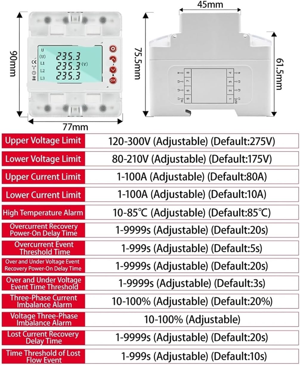
Figure 4.1: Dimensions and adjustable parameter ranges for the EAEMP3-100-TY-W.
| Parameter | Value / Range |
|---|---|
| Model | EAEMP3-100-TY-W |
| Rated Voltage | 380V (3-Phase) |
| Maximum Operating Current | 100A (Adjustable 1-100A) |
| Output Voltage Range | 80-300V |
| Accuracy Level | 1% |
| Upper Voltage Limit | 120-300V (Default: 275V) |
| Lower Voltage Limit | 80-210V (Default: 175V) |
| Upper Current Limit | 1-100A (Default: 80A) |
| Lower Current Limit | 1-100A (Default: 10A) |
| High Temperature Alarm | 10-85°C (Default: 85°C) |
| Overcurrent Recovery Power-On Delay Time | 1-9999s (Default: 20s) |
| Overcurrent Event Threshold Time | 1-9999s (Default: 5s) |
| Over and Under Voltage Event Recovery Power-On Delay Time | 1-9999s (Default: 20s) |
| Over and Under Voltage Event Time Threshold | 1-9999s (Default: 3s) |
| Three-Phase Current Imbalance Alarm | 10-100% (Default: 20%) |
| Voltage Three-Phase Imbalance Alarm | 10-100% (Adjustable) |
| Lost Current Recovery Delay Time | 1-9999s (Default: 20s) |
| Time Threshold of Lost Flow Event | 1-9999s (Default: 10s) |
| Package Dimensions | 1.18 x 0.79 x 0.39 inches |
| Item Weight | 1.76 ounces |
5. Installation
5.1 Wiring Diagram

Figure 5.1: Wiring connections for the EAEMP3-100-TY-W. Connect L1, L2, L3, and Neutral (N) as indicated by the labels and arrows.
5.2 Installation Steps
- Power Disconnection: Ensure all power to the installation area is completely disconnected at the main breaker.
- Mounting: Mount the device securely on a DIN rail within an appropriate electrical enclosure.
- Wiring:
- Connect the three-phase live wires (L1, L2, L3) to their respective terminals on the device.
- Connect the Neutral (N) wire to the designated neutral terminal.
- Ensure all connections are tight and secure to prevent loose contacts and overheating.
- Verification: Double-check all wiring against the diagram (Figure 5.1) before restoring power.
- Power Restoration: Carefully restore power to the system. The device display should illuminate.
6. Setup and Configuration
6.1 Parameter Settings
Figure 6.1: Setting parameter flow chart and Wi-Fi indicator status.
- Enter Settings: Long press and hold the Setting button (top right button with gear icon, visible in Figure 3.1) to enter the setting status display page. The data bits will flash.
- Adjust Value: Use the Up (second button from top right, visible in Figure 3.1) and Down (third button from top right, visible in Figure 3.1) buttons to set the content of the flashing data bit.
- Switch Bit/Parameter: Short press the Setting button to switch to the next setting bit or parameter.
- Confirm and Next: Short press the OK button (bottom right button, visible in Figure 3.1) to confirm the settings on the current page and jump to the next settings page.
- Exit and Save: Long press the OK button to exit the setting state and save all configured settings.
Refer to the "Specifications" section (Table 4.1) for the adjustable ranges and default values of each parameter, including voltage limits, current limits, and various delay times.
6.2 Wi-Fi Connection (for "TY" models)
The "TY" in the model name indicates Wi-Fi connectivity for remote monitoring and control. Follow these steps to connect to Wi-Fi:
- Wi-Fi Indicator Light Status:
- Fast flashing: Indicates the device is searching for a Wi-Fi signal.
- Slow flashing: Indicates Wi-Fi is offline.
- Long light (solid): Indicates that Wi-Fi is connected.
- Manual Connection: If the device does not connect to Wi-Fi automatically, long-press the third key on the screen (which shows voltage, typically the 'Down' button) for three seconds to initiate the connection process.
7. Operating Instructions
7.1 Display Information
Once powered on, the device's digital display will show real-time electrical parameters. This typically includes:
- Voltage for each phase (L1, L2, L3)
- Total voltage (U)
- Current for each phase
- Active Power (kW)
- Reactive Power (kVAR)
- Apparent Power (kVA)
- Power Factor (PF)
- Frequency (Hz)
- Total Energy (kWh) - Import and Export
Use the navigation buttons (Up/Down, visible in Figure 3.1) to cycle through different display screens and view various parameters.
7.2 Protection Functions
The device automatically monitors the electrical system and activates protection mechanisms based on the configured settings:
- Over-Voltage Protection: If any phase voltage exceeds the "Upper Voltage Limit" for the "Over and Under Voltage Event Time Threshold", the device will trip and disconnect the load.
- Under-Voltage Protection: If any phase voltage drops below the "Lower Voltage Limit" for the "Over and Under Voltage Event Time Threshold", the device will trip and disconnect the load.
- Over-Current Protection: If the current in any phase exceeds the "Upper Current Limit" for the "Overcurrent Event Threshold Time", the device will trip and disconnect the load.
- High Temperature Alarm: An alarm will be triggered if the internal temperature exceeds the "High Temperature Alarm" threshold.
- Automatic Reconnection: After a protection event, the device will automatically attempt to reconnect after the respective recovery delay time (e.g., "Overcurrent Recovery Power-On Delay Time", "Over and Under Voltage Event Recovery Power-On Delay Time") has elapsed and the fault condition has cleared.
8. Maintenance
The EAEMP3-100-TY-W is designed for reliable operation with minimal maintenance. However, periodic checks are recommended:
- Visual Inspection: Regularly inspect the device and its wiring for any signs of damage, loose connections, or discoloration.
- Cleaning: Keep the device clean and free from dust. Use a soft, dry cloth for cleaning. Do not use liquid cleaners or solvents.
- Environment: Ensure the operating environment remains within the specified temperature and humidity ranges.
- Firmware Updates: Check the manufacturer's website periodically for any available firmware updates, especially for Wi-Fi enabled models, to ensure optimal performance and security.
9. Troubleshooting
| Problem | Possible Cause | Solution |
|---|---|---|
| Device display is off. | No power supply; incorrect wiring; internal fault. | Check main power supply. Verify wiring connections. If problem persists, contact support. |
| Device trips frequently. | Voltage/current outside set limits; incorrect settings; actual fault in system. | Check system voltage/current. Review and adjust protection settings. Investigate for actual electrical faults. |
| Incorrect readings on display. | Loose wiring; faulty sensor; device malfunction. | Ensure all wiring is secure. If readings are consistently inaccurate, contact support. |
| Wi-Fi not connecting (for "TY" models). | Incorrect Wi-Fi password; out of range; network issues; device not in pairing mode. | Check Wi-Fi network and password. Ensure device is within Wi-Fi range. Long-press the third key on the screen for 3 seconds to initiate connection. |
10. Warranty and Support
For warranty information, technical support, or service inquiries, please contact your retailer or the manufacturer, EGBYXSAP, directly. Keep your purchase receipt as proof of purchase for warranty claims.
Manufacturer: EGBYXSAP