Todikaper PF959LP918IM94XO78HZU760
User Manual: Todikaper Single Phase to Three Phase Inverter
Model: UX-52-100-1.1KW (PF959LP918IM94XO78HZU760)
1. Introduction
This manual provides essential information for the safe and efficient operation of your Todikaper Single Phase to Three Phase Inverter. Please read this manual thoroughly before installation, operation, or maintenance to ensure proper use and to prevent damage to the unit or injury to personnel. Keep this manual for future reference.
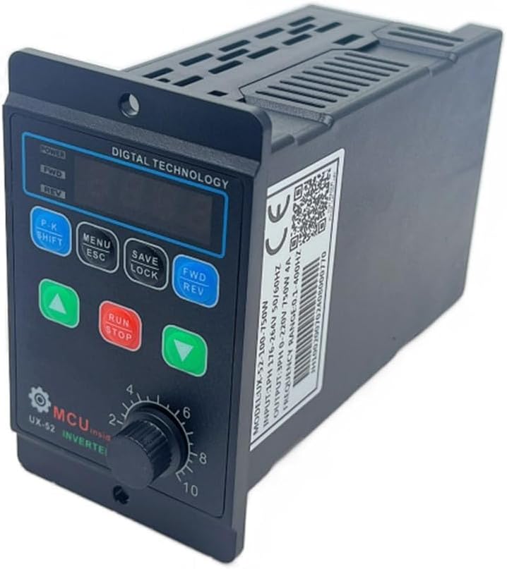
Figure 1.1: Angled view of the Todikaper Single Phase to Three Phase Inverter, showcasing its compact design and digital display.
2. Safety Information
Always observe the following safety precautions to reduce the risk of electric shock, fire, or injury.
- Ensure the power supply is disconnected before any installation, wiring, or maintenance.
- Only qualified personnel should perform installation and wiring.
- Do not operate the inverter with wet hands or in damp environments.
- Ensure proper grounding to prevent electric shock.
- Do not disassemble or modify the inverter. Refer all servicing to qualified service personnel.
- Protect the unit from direct sunlight, excessive heat, dust, and corrosive gases.
3. Product Overview
The Todikaper Variable Frequency Drive (VFD) is designed to convert single-phase 220V input into three-phase 220V output, suitable for controlling the speed of 3-phase motors. It features a digital display for easy monitoring and control.
3.1 Key Features
- Versatile Input/Output: Single-phase 220V input to three-phase 220V output.
- Power Range: 750W / 1100W models available.
- Frequency Range: 1.0-99Hz for precise motor speed control.
- Safety Protections: Includes overvoltage, short-circuit, and overcurrent protection.
- Intuitive Digital Display: Simplifies monitoring and setting adjustments.
- Adaptive Voltage Handling: Supports input voltages from 80-280V.

Figure 3.1: Front view of the VFD, showing the digital display, control buttons (P.K SHIFT, MENU ESC, SAVE LOCK, FWD REV, and directional arrows), and the speed control knob.

Figure 3.2: This image highlights the key features of the VFD, including its programmable motor speed control, high-performance MPU for efficient and reliable operation, and built-in safety protections against overload and over-temperature.
3.2 Components
- Digital Display: Shows frequency, speed, and error codes.
- Control Buttons: For navigation, setting adjustments, and operation control.
- Speed Control Knob: Manual adjustment of output frequency/motor speed.
- Input/Output Terminals: For power and motor connections.
- Cooling Fan/Vents: For heat dissipation.

Figure 3.3: Side view of the VFD, illustrating the ventilation design for effective heat dissipation during operation.
4. Setup and Installation
Proper installation is crucial for the performance and longevity of the inverter. Ensure all connections are secure and correct.
4.1 Mounting
Mount the inverter in a well-ventilated area, away from direct sunlight, moisture, and excessive dust. Ensure sufficient clearance around the unit for airflow.
4.2 Wiring Connections
Refer to the wiring diagram below for correct connections. Always ensure power is OFF before making any connections.
- AC 220V Input: Connect your single-phase 220V power supply to the input terminals (L, N).
- Ground Connection: Connect the ground wire to the FG terminal.
- Motor Output: Connect the three-phase motor wires (U, V, W) to the corresponding output terminals.

Figure 4.1: Detailed wiring diagram illustrating the connections for AC 220V input, ground, and the U, V, W outputs to the three-phase motor. Ensure all connections are secure and follow local electrical codes.

Figure 4.2: This image visually confirms the inverter's capability to accept a single-phase input ranging from 110-220V and provide a three-phase output within the 110-220V range, suitable for various motor applications.
5. Operating Instructions
This section details the basic operation of the VFD using its control panel.
Figure 5.1: The control panel of the VFD, featuring the digital display, function buttons, and speed control knob for manual adjustments.
5.1 Powering On/Off
- To power on, ensure all connections are correct, then apply single-phase 220V power. The digital display will illuminate.
- To power off, disconnect the main power supply.
5.2 Basic Operation
- Start Motor: Press the RUN button to start the motor. The display will show the current output frequency.
- Stop Motor: Press the STOP button to stop the motor.
- Adjust Speed: Rotate the speed control knob to increase or decrease the motor speed. The display will update to show the new frequency.
- Change Direction: Press the FWD REV button to toggle between forward and reverse rotation.
5.3 Menu Navigation and Settings
The VFD allows for advanced parameter adjustments through its menu system.
- Press MENU ESC to enter or exit the menu.
- Use the UP and DOWN arrow buttons to navigate through menu parameters.
- Press P.K SHIFT to select a parameter or shift digits during value entry.
- Press SAVE LOCK to save changes or lock the keypad.
Refer to the detailed parameter list in the full technical manual for specific settings and their functions.
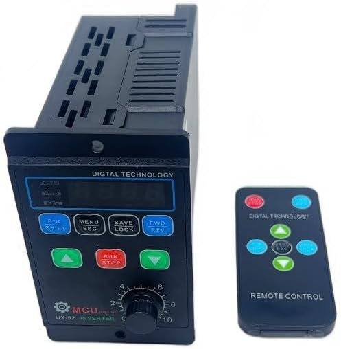
Figure 5.2: The VFD can also be controlled remotely using the provided remote control, offering convenience for operation from a distance.
6. Maintenance
Regular maintenance ensures optimal performance and extends the lifespan of your inverter.
- Cleaning: Periodically clean the exterior of the unit with a soft, dry cloth. Do not use liquid cleaners or solvents.
- Ventilation: Ensure cooling vents are free from dust and obstructions. Use compressed air to clear dust if necessary.
- Connections: Periodically check all wiring connections for tightness and signs of wear or corrosion.
- Storage: If storing the unit for an extended period, keep it in a dry, cool, and dust-free environment.
7. Troubleshooting
This section provides solutions to common issues you might encounter.
| Problem | Possible Cause | Solution |
|---|---|---|
| No power on display | No input power; loose connection; faulty power supply. | Check power source; verify all input wiring; test power supply. |
| Motor not running | Incorrect wiring; motor overload; VFD in stop mode; parameter error. | Verify motor wiring (U, V, W); check motor load; press RUN; reset parameters to default if necessary. |
| Motor runs erratically | Unstable input voltage; motor not compatible; interference. | Ensure stable input voltage (80-280V); confirm motor compatibility; check for external interference. |
| Overload error (e.g., "OC" or "OL") | Motor drawing too much current; VFD capacity too low for motor. | Reduce motor load; ensure VFD matches motor power requirements; check motor for faults. |
If the problem persists after attempting these solutions, contact customer support.
8. Specifications
Technical specifications for the Todikaper Single Phase to Three Phase Inverter.
| Parameter | Value |
|---|---|
| Model | UX-52-100-1.1KW (PF959LP918IM94XO78HZU760) |
| Input Voltage | Single-phase 80-280V AC |
| Output Voltage | Three-phase 220V AC |
| Power Rating | 750W / 1100W (depending on variant) |
| Output Frequency | 1.0 - 99Hz |
| Material | ABS |
| Dimensions (L x W x H) | 147mm x 60mm x 102mm (approx. 18 x 13 x 9 cm as per product data) |
| Color | Black |
9. Warranty and Support
For warranty information or technical support, please contact your retailer or the manufacturer directly. Keep your purchase receipt as proof of purchase.
Manufacturer: Todikaper
Ask a question about this manual
Ask about setup, troubleshooting, compatibility, parts, safety, or missing instructions. Manuals+ will review the question and use this page’s manual context to help answer it.