1. Introduction
This manual provides essential information for the installation, operation, maintenance, and troubleshooting of the XCHANG Air Conditioner Outdoor PCB Assembly. This inverter printed circuit board is compatible with LG air conditioning units and is designed for commercial applications. Please read this manual thoroughly before proceeding with any procedures to ensure correct usage and safety.
2. Safety Information
Warning: Electrical components can be hazardous. Installation and servicing should only be performed by qualified and experienced personnel. Failure to follow these instructions may result in electric shock, fire, or property damage.
- Always disconnect power to the air conditioning unit before attempting any installation, maintenance, or repair.
- Wear appropriate personal protective equipment (PPE), including insulated gloves and safety glasses.
- Ensure proper grounding of the air conditioning unit.
- Do not touch live electrical components.
- Verify all connections are secure and correct before restoring power.
3. Product Overview
The XCHANG Outdoor PCB Assembly is a critical component for the inverter control system of compatible LG air conditioners. It manages various functions of the outdoor unit, including compressor operation, fan speed, and communication with the indoor unit.

Figure 3.1: Main view of the XCHANG Air Conditioner Outdoor PCB Assembly. This image displays the top side of the circuit board with various electronic components, including large capacitors, relays, and integrated circuits, mounted on a green PCB within a black frame.
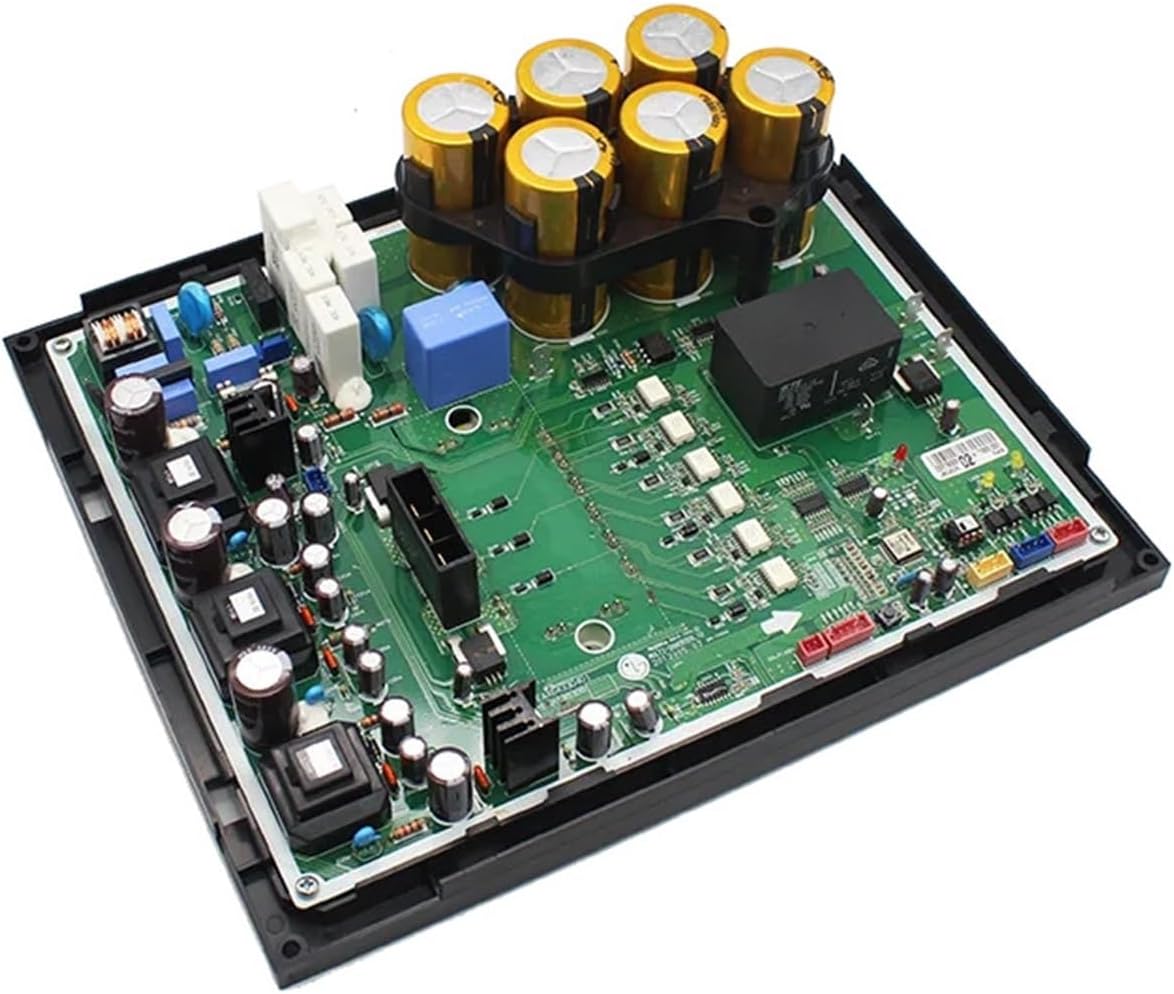
Figure 3.2: Angled view of the XCHANG Air Conditioner Outdoor PCB Assembly. This perspective highlights the three-dimensional arrangement of components, showing the height of the capacitors and other modules on the circuit board.

Figure 3.3: Close-up of PCB markings and components. This detailed image shows specific labels such as "EAX64330401" and "EBR73830801" printed on the circuit board, along with smaller surface-mount components and connection points.

Figure 3.4: Close-up of capacitors on the PCB. This image focuses on the bank of large, cylindrical capacitors, which are crucial for power filtering and energy storage within the inverter circuit.

Figure 3.5: Rear view of the PCB Assembly. This image shows the underside of the circuit board, typically revealing solder points and a heat sink plate for thermal management.
4. Installation
This PCB assembly is a replacement part and does not require assembly of individual components. Professional installation is highly recommended due to the complex nature of air conditioning systems and high voltage components.
4.1. Pre-Installation Steps
- Disconnect Power: Ensure the main power supply to the air conditioning unit is completely disconnected at the circuit breaker. Verify with a voltage tester.
- Access Outdoor Unit: Open the outdoor unit casing to access the existing PCB.
- Document Connections: Take clear photographs or make detailed diagrams of all wiring connections to the old PCB before disconnecting them. This is crucial for correct re-connection.
- Discharge Capacitors: If applicable, safely discharge any large capacitors on the old PCB before handling.
4.2. Replacement Procedure
- Remove Old PCB: Carefully disconnect all wires and mounting screws securing the old PCB. Remove it from the unit.
- Install New PCB: Position the new XCHANG PCB Assembly in the same location as the old one. Secure it with the appropriate mounting screws.
- Connect Wiring: Refer to your documented connections (photos/diagrams) and carefully re-connect all wires to the new PCB. Ensure each wire is securely fastened to its correct terminal.
- Inspect Connections: Double-check all wiring for proper seating and absence of loose connections or pinched wires.
4.3. Post-Installation Steps
- Close Unit: Securely close the outdoor unit casing.
- Restore Power: Reconnect the main power supply to the air conditioning unit at the circuit breaker.
- Test Operation: Power on the air conditioner and verify its normal operation, including cooling/heating, fan functions, and any specific modes.
5. Operational Features
The outdoor PCB assembly facilitates several key operational features of the air conditioning system:
- Wind Speed Control: The PCB supports various wind speed adjustment options, allowing the system to achieve optimal air circulation and comfort based on user settings from the indoor unit's control panel.
- Timer Function: It enables the air conditioner's timer on/off function, allowing users to preset operational schedules to conserve energy and ensure the unit operates only when needed.
- Communication Interface: Advanced versions of this control board may include communication interfaces for integration with smart home systems or central control units, enabling remote monitoring and control capabilities.
6. Maintenance
Regular maintenance helps ensure the longevity and efficient operation of the PCB assembly and the entire air conditioning unit. Always disconnect power before performing any maintenance.
- Visual Inspection: Periodically inspect the PCB for any signs of damage, such as burnt components, swollen capacitors, or loose connections.
- Cleaning: Gently clean any dust or debris accumulated on the PCB using a soft brush or compressed air. Avoid using liquids.
- Connection Check: Ensure all wire connections to the PCB remain tight and free from corrosion.
7. Troubleshooting
The control board includes a fault diagnosis function to assist in identifying issues within the air conditioning system.
- Fault Codes: If the air conditioner malfunctions, the control board can detect and display corresponding fault codes. Refer to your air conditioner's specific service manual for the meaning of these codes to diagnose the problem.
- No Power: Check the main power supply, circuit breaker, and all power connections to the outdoor unit and PCB.
- Unit Not Responding: Verify all communication wires between the indoor and outdoor units are correctly connected and undamaged.
- Abnormal Operation: If the unit exhibits unusual behavior (e.g., incorrect fan speed, compressor cycling issues), consult a qualified technician.
For complex issues or if fault codes persist after basic checks, contact a certified HVAC technician for professional diagnosis and repair.
8. Specifications
| Feature | Specification |
|---|---|
| Model Numbers | EBR73830801, EBR73830802, EAX64330401 |
| Type | Inverter PCB Assembly |
| Application | Commercial Air Conditioners (LG Compatible) |
| Voltage | 380V (as per product description) |
| Package Dimensions | 1.18 x 0.79 x 0.39 inches |
| Item Weight | 1.76 ounces |
| Assembly Required | No (pre-assembled unit) |
| Number of Pieces | 1 |
| Manufacturer | changjucai |
9. Warranty and Support
For information regarding product warranty, returns, or technical support, please refer to the terms and conditions provided by your retailer or contact the manufacturer directly. Keep your purchase receipt as proof of purchase.