1. Introduction
This manual provides comprehensive instructions for the installation, operation, and maintenance of your PowMr 60A MPPT Solar Charge Controller. This device is designed to efficiently manage power flow from solar panels to batteries, ensuring optimal charging and extending battery lifespan. Please read this manual thoroughly before installation and operation to ensure safe and correct usage.
Key Features:
- Advanced MPPT Technology: Achieves high efficiency (≥98.1%) and PV utilization (≥99%) for maximum power point tracking.
- Automatic Voltage Detection: Automatically detects 12V/24V/36V/48V battery systems.
- Wide Battery Compatibility: Supports various battery types including Lithium, LiFePO4, Li(NiCoMn)O2, Vented, Flooded, Sealed, Gel, and NiCd. User-programmable settings for custom battery types.
- Comprehensive Protection: Features a backlight LCD for real-time monitoring of PV voltage, output power, battery voltage, charging current, working mode, and temperature. Includes troubleshooting functions.
- Efficient Cooling System: Updated bladeless fan system for quiet and efficient heat dissipation, activating above 45℃ and deactivating below 40℃.
- Plug-and-Play Temperature Sensor: Includes an external temperature probe for accurate battery temperature compensation.
- Parallel Capability: Supports up to 12 parallel connections for increased system capacity.
2. Safety Instructions
Adhering to these safety guidelines is crucial for preventing personal injury and damage to the equipment. Always follow local electrical codes and regulations.
- Ensure all power sources (solar panels, battery) are disconnected before installation or maintenance.
- Use insulated tools to prevent electrical shock.
- Install the controller in a well-ventilated area, away from flammable materials and direct sunlight.
- Do not disassemble or attempt to repair the controller yourself. Refer to qualified personnel.
- Verify correct polarity for all connections (PV, battery, load) before applying power. Incorrect wiring can cause severe damage.
- Ensure battery voltage exceeds 12V for controller activation and self-detection upon connection.
- Use appropriate wire gauges for all connections to prevent overheating. The product supports 9AWG copper wires for solar and battery connectors.
- Keep children away from the solar power system.
3. Product Overview
The PowMr 60A MPPT Solar Charge Controller is designed with user-friendliness and durability in mind. It features a clear LCD display and intuitive controls for easy monitoring and configuration.

Figure 3.1: Front view of the PowMr 60A MPPT Solar Charge Controller, showing the LCD display, control buttons (PRG/ESC, Up, Down, ENTER), and terminal connections at the bottom for PV, Battery, and Load.
Components and Display:
- LCD Display: Shows real-time system parameters such as PV voltage, output power, battery voltage, charging current, working mode, and temperature.
- Control Buttons:
- PRG/ESC: Program/Escape button, used to enter or exit programming mode.
- Up Arrow: Navigates up through menus or increases values.
- Down Arrow: Navigates down through menus or decreases values.
- ENTER: Confirms selections or enters sub-menus.
- Terminal Connections: Clearly labeled terminals for connecting solar panels (PV), batteries, and DC loads. Each positive and negative connection has two terminals for convenience.
- Temperature Sensor Port: Dedicated port for the external temperature probe.
- Cooling Fan: Integrated bladeless fan for efficient heat dissipation.

Figure 3.2: Dimensions of the PowMr 60A MPPT Solar Charge Controller. The unit measures approximately 5.12 inches (13 cm) in length, 3.35 inches (8.5 cm) in width, and 8.46 inches (21.5 cm) in height.
4. Setup and Installation
Proper installation is critical for the performance and longevity of your solar charge controller. Follow these steps carefully.
4.1 Wiring Sequence:
Always connect components in the following order to prevent damage:
- Connect the Battery: First, connect the battery to the controller's battery terminals. Ensure correct polarity (+ to + and - to -). The controller will automatically detect the battery voltage. Ensure the battery voltage is above 12V for proper activation.
- Connect the Solar Panels (PV): Next, connect the solar panels to the controller's PV terminals. Ensure correct polarity. The controller will begin charging the battery.
- Connect the DC Load (Optional): Finally, connect any DC loads to the controller's load terminals.

Figure 4.1: A typical solar power system connection diagram. The PowMr MPPT Solar Controller connects solar panels to the battery bank. A DC load can be directly connected to the controller, while an AC load requires an inverter connected to the battery. The diagram also illustrates support for parallel connections of multiple controllers and solar panels.
4.2 Temperature Sensor Installation:
The included external temperature probe should be connected to the dedicated port on the controller and placed near the battery. This allows the controller to accurately compensate charging voltage based on battery temperature, optimizing charging efficiency and battery life.

Figure 4.2: Illustration of the plug-and-play temperature sensor connected to the PowMr solar charge controller. The sensor cable extends from the controller to the battery, ensuring accurate temperature readings for optimized charging.
4.3 Parallel Connections:
This controller supports up to 12 units connected in parallel to increase the overall system charging capacity. Refer to Figure 4.1 for a visual representation of parallel controller connections. Ensure all controllers are configured identically when operating in parallel.
5. Operating Instructions
Once installed, the controller will automatically begin operation. Use the LCD display and buttons to monitor system status and adjust settings if necessary.
5.1 LCD Display and Navigation:
The backlight LCD displays various parameters. Use the Up and Down arrow buttons to scroll through different screens. Press ENTER to view detailed information or enter a setting menu. Press PRG/ESC to exit a menu or return to the previous screen.
5.2 Battery Type Settings:
The controller is compatible with multiple battery types. For sealed lead-acid, vented, or gel batteries, no parameter settings are typically needed as the controller adjusts automatically. However, for lithium batteries (e.g., LiFePO4, Li(NiCoMn)O2), manual parameter adjustment is required due to their specific voltage characteristics. Refer to your battery's specifications for correct voltage settings (absorption voltage, floating voltage, low voltage disconnect).

Figure 5.1: The PowMr MPPT Solar Charge Controller is compatible with various battery types, including Sealed, Lead-acid, Lithium, Gel, and Flooded batteries. It employs a 4-stage charging algorithm for rapid, efficient, and safe charging across 12V, 24V, 36V, and 48V battery systems, boasting high tracking efficiency (99%) and peak conversion efficiency (98%).
5.3 Charging Stages:
The controller utilizes an intelligent multi-stage charging algorithm to optimize battery charging and extend battery life. These stages typically include:
- Bulk Charge: Delivers maximum current to rapidly charge the battery until it reaches a set voltage.
- Boost Charge: Continues charging at a higher voltage for a set period to ensure full charge and equalization (if applicable).
- Float Charge: Maintains the battery at a constant, lower voltage to prevent self-discharge and overcharging.
- Equalization Charge (for certain battery types): Periodically overcharges the battery slightly to balance cell voltages and prevent sulfation.

Figure 5.2: Visual representation of the 4-stage battery charging process: Bulk, Boost, Float, and Equalization. This intelligent charging method effectively prevents battery overcharging or over-discharging, significantly extending battery life.
5.4 Thermal Management:
The controller features an updated bladeless fan system for efficient heat dissipation. The fan activates automatically when the internal temperature exceeds 45℃ and turns off when it drops below 40℃, ensuring stable operation and longevity.
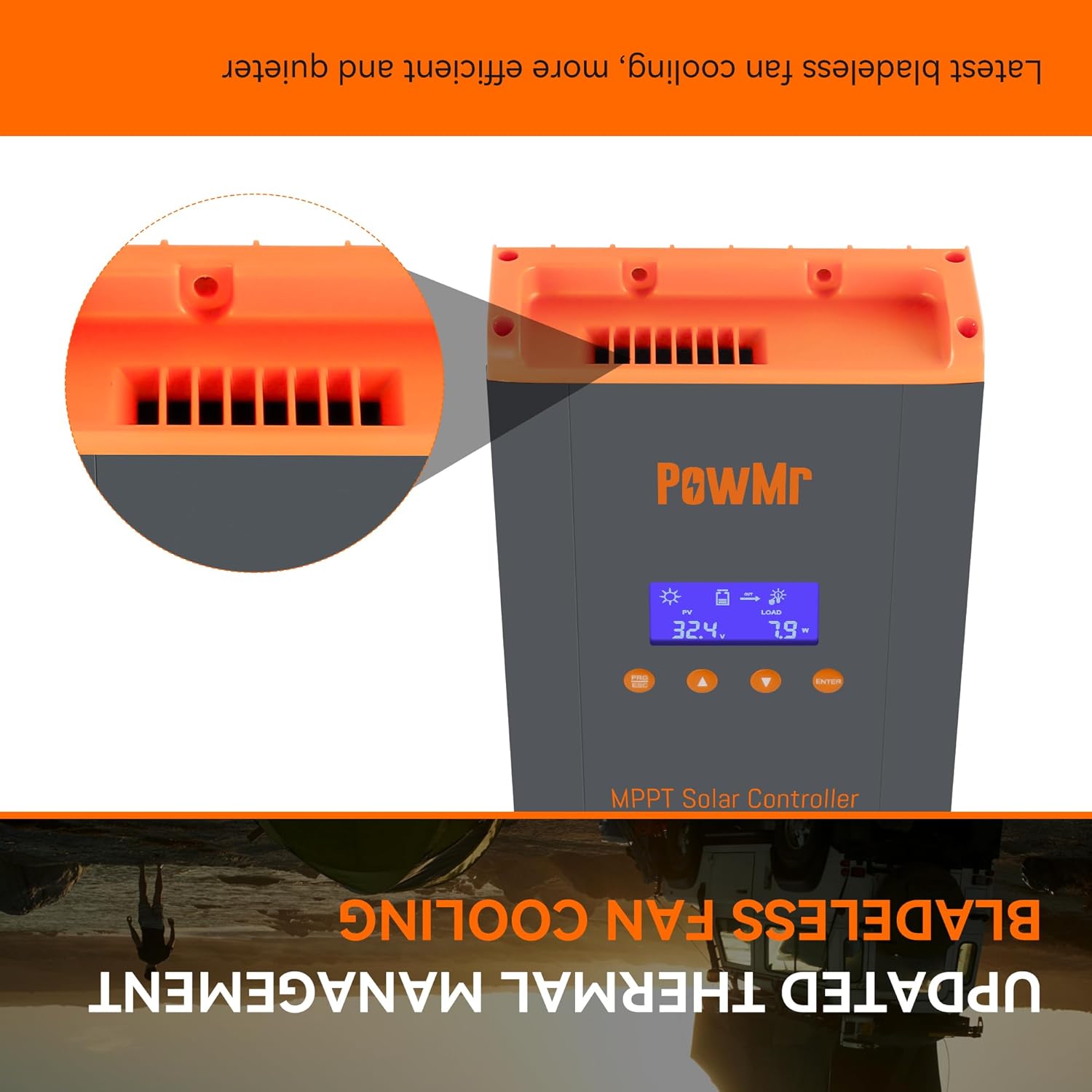
Figure 5.3: Close-up view of the updated bladeless fan cooling system integrated into the PowMr solar charge controller, designed for quieter and more efficient thermal management.
6. Maintenance
Regular maintenance ensures optimal performance and extends the lifespan of your solar charge controller.
- Check Connections: Periodically inspect all wiring connections for tightness and corrosion. Loose connections can cause overheating and poor performance.
- Cleanliness: Keep the controller clean and free from dust and debris. Ensure ventilation openings are not blocked. Use a dry cloth for cleaning.
- Environmental Check: Ensure the installation environment remains within the specified operating temperature range and is free from excessive humidity or corrosive gases.
- Battery Health: Monitor battery health and electrolyte levels (for flooded batteries) as per battery manufacturer guidelines.
7. Troubleshooting
The controller includes a troubleshooting function to help identify and resolve common issues. The LCD display may show error codes or warnings. Refer to the display for specific fault indications.
Common Issues and Solutions:
- No Display/No Power:
- Check battery connections and ensure battery voltage is above 12V.
- Verify battery fuse or circuit breaker is not tripped.
- No Charging:
- Check solar panel connections and polarity.
- Ensure sufficient sunlight is reaching the solar panels.
- Verify PV input voltage is within the controller's operating range.
- Low Charging Current:
- Check for shading on solar panels.
- Ensure wire gauges are adequate for the current.
- Verify battery is not already full or in float charge stage.
- Over-temperature Warning:
- Ensure adequate ventilation around the controller.
- Check if the cooling fan is operating correctly.
- Clear any obstructions from the fan vents.
- Incorrect Battery Voltage Reading:
- Ensure the temperature sensor is properly connected and placed near the battery.
- Verify battery type settings are correct, especially for lithium batteries.
For persistent issues or error codes not listed, please contact PowMr customer support.
8. Specifications
| Feature | Specification |
|---|---|
| Model Number | HHJ60-PRO |
| Brand | PowMr |
| Rated Charge Current | 60A |
| System Voltage | 12V/24V/36V/48V Auto Detection |
| Max. PV Input Voltage | 160V DC |
| Max. PV Input Power (12V system) | 720W |
| Max. PV Input Power (24V system) | 1440W |
| Max. PV Input Power (36V system) | 2100W |
| Max. PV Input Power (48V system) | 2800W |
| Display Type | LCD |
| Operating Temperature | Up to 45°C (113°F) |
| Product Dimensions (L x W x H) | 5.12 x 3.35 x 8.46 inches (13 x 8.5 x 21.5 cm) |
| Item Weight | 2.16 pounds (0.98 kg) |
| Included Components | Controller, Parallel Terminal, External temperature probe |
| Country of Origin | China |
9. Warranty and Support
For warranty information, technical support, or service inquiries, please contact PowMr customer service through their official website or the retailer from whom you purchased the product. Please have your model number (HHJ60-PRO) and purchase details ready when contacting support.
Regularly check the manufacturer's website for updated manuals, firmware, and support resources.