1. Introduction
The JESSINIE LCUS-2 USB 2-Channel Relay Module is designed for intelligent control of various devices through a USB serial interface. This module allows for precise automation tasks in home automation, industrial control, and other applications requiring remote switching. It features two independent relay channels, robust protection mechanisms, and a user-friendly communication protocol.
2. Product Features
- Intelligent USB Switching: Enables seamless control of devices for automation tasks via USB serial instructions.
- High-Performance Relays: Equipped with two 5V, 10A relays supporting up to 250VAC/30VDC, designed for over 100,000 cycles.
- Advanced Protection: Features built-in overcurrent protection and relay diode freewheeling protection to safeguard connected devices.
- User-Friendly Protocol: Simplified communication protocol with a default baud rate of 9600BPS, compatible with standard serial debugging software.
- Compact Design: Measures approximately 50mm x 40mm, allowing for easy integration into various systems.

Figure 1: Top and bottom view of the JESSINIE LCUS-2 USB 2-Channel Relay Module.
3. Package Contents
The package includes:
- 1 x JESSINIE LCUS-2 USB 2-Channel Relay Module
4. Specifications
| Feature | Specification |
|---|---|
| Model Number | LCUS-2 (83519JE) |
| Number of Channels | 2 |
| Relay Voltage/Current | 5V, 10A (250VAC/30VDC) |
| Communication Interface | Micro USB (Serial) |
| Default Baud Rate | 9600 BPS |
| Product Dimensions | 50mm x 40mm (approx. 3.15 x 1.18 x 0.47 inches) |
| Weight | 1.41 ounces |
| Contact Material | Copper |
| Contact Type | Normally Open (NO) |
| Mounting Type | PCB Mount |

Figure 2: Physical dimensions of the LCUS-2 module.
5. Setup Instructions
5.1 Driver Installation
The LCUS-2 module uses a CH340 USB to serial chip. Before connecting the module, ensure the appropriate CH340 driver is installed on your computer. Drivers are typically available from the chip manufacturer's website or can be found through a general online search for 'CH340 driver'.
5.2 Physical Connections
Connect the module to your computer using a Micro USB cable. The module can be powered via the USB connection. For relay connections, refer to the pinout diagram below:
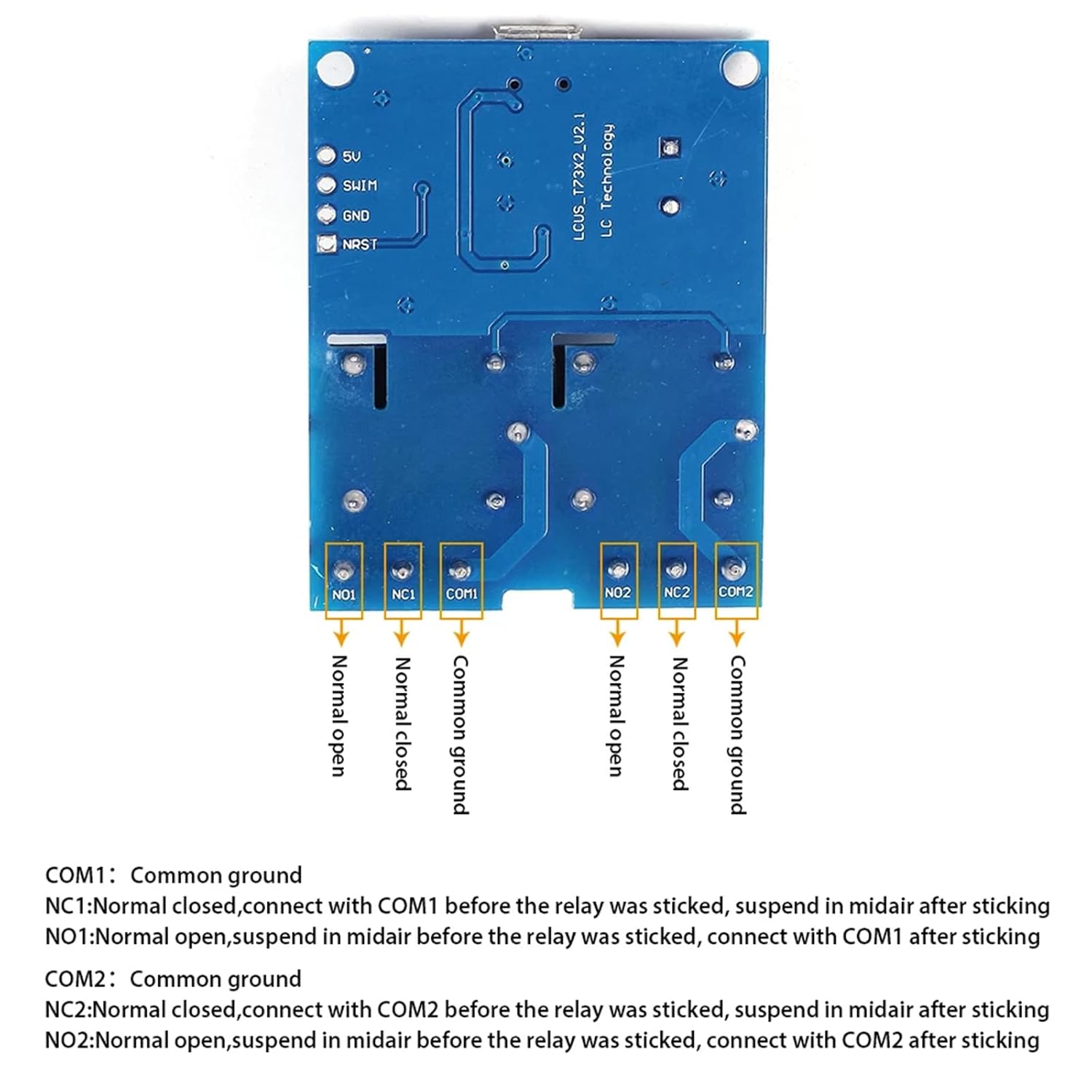
Figure 3: Pinout diagram for relay connections.
- COM1: Common terminal for Relay 1.
- NC1: Normally Closed terminal for Relay 1. Connect to COM1 before the relay is activated.
- NO1: Normally Open terminal for Relay 1. Connects to COM1 after the relay is activated.
- COM2: Common terminal for Relay 2.
- NC2: Normally Closed terminal for Relay 2. Connect to COM2 before the relay is activated.
- NO2: Normally Open terminal for Relay 2. Connects to COM2 after the relay is activated.
Ensure all connections are secure. When using the screw terminals, carefully insert the wire and tighten the screw to avoid the wire being pushed out.
6. Operating Instructions
6.1 Communication Protocol
The module communicates via a serial interface using hexadecimal commands. The default communication baud rate is 9600 BPS.
Command Structure:
Each command consists of four bytes:
- Data (1) - Start Flag: Always
0xA0. - Data (2) - Switch Address:
0x01for the first relay,0x02for the second relay. - Data (3) - Operating Data:
0x00for OFF,0x01for ON. - Data (4) - Check Code (Checksum): The sum of Data (1), Data (2), and Data (3).
Example Commands:
- Turn ON Relay 1:
A0 01 01 A2(0xA0 + 0x01 + 0x01 = 0xA2) - Turn OFF Relay 1:
A0 01 00 A1(0xA0 + 0x01 + 0x00 = 0xA1) - Turn ON Relay 2:
A0 02 01 A3(0xA0 + 0x02 + 0x01 = 0xA3) - Turn OFF Relay 2:
A0 02 00 A2(0xA0 + 0x02 + 0x00 = 0xA2)
When sending commands in quick succession, it is recommended to include a short pause (e.g., 50ms) between commands to ensure proper processing by the module.
6.2 Relay Status Query
To query the current status of the relays, send the hexadecimal command 0xFF.
The module will respond with a sequence of bytes indicating the status of each relay. For a 2-channel module, the response will typically be two bytes, where 01 signifies the relay is ON and 00 signifies the relay is OFF. For example, if Relay 1 is ON and Relay 2 is OFF, the response might be 01 00.

Figure 4: Internal schematic diagram of the LCUS-2 module.
7. Maintenance
The JESSINIE LCUS-2 module is designed for durability and requires minimal maintenance. Keep the module clean and free from dust and moisture. Avoid exposing it to extreme temperatures or corrosive environments. Periodically check all wiring connections for tightness and integrity.
8. Troubleshooting
- Module Not Recognized: Ensure the CH340 USB to serial driver is correctly installed. Try a different USB port or cable. Some USB cables may be incompatible.
- Commands Not Responding: Verify the baud rate is set to 9600 BPS in your serial communication software. Confirm that commands are sent in the correct hexadecimal format, including the accurate checksum. If sending multiple commands rapidly, introduce a 50ms pause between each command.
- Relay Connections Loose: If a connected device is not switching reliably, check the screw terminals. Ensure wires are properly inserted and the screws are tightened securely. Avoid over-tightening, which can damage the terminal.
- Incorrect Relay Status: Double-check the command sent for querying status (0xFF). Ensure your software is interpreting the received hexadecimal response correctly.
9. Warranty and Support
For warranty information or technical support, please refer to the product's purchase platform or contact JESSINIE customer service directly. Specific warranty details may vary by region and retailer.