
1. Product Overview
The LVSEDTAL MPPT Solar Hybrid Inverter 5KW is a versatile power solution designed to integrate solar, utility, and battery power sources. This inverter is capable of operating without a battery, providing a reliable energy supply for various applications. It features an advanced MPPT solar charger controller and a pure sine wave output for sensitive electronics.

Figure 1.1: General view of the LVSEDTAL MPPT Solar Hybrid Inverter.
Key Features:
- Stability: Engineered for long-term stable operation.
- Flexible Power Source Compatibility: Supports charging from solar, utility, or generator power. Allows for flexible scheduling of inverter charging and discharging times.
- Wide Application: Ideal for use as a backup power supply during utility outages.
- User-Friendly Interface: Equipped with an LCD display controller for easy access to operating parameters, including battery status and operating temperature.
- Comprehensive Protections: Includes temperature-controlled cooling fan, low and high voltage protection, overload protection, short circuit protection, internal fuse, and battery reverse connection protection.
2. Safety Information
Please read all instructions and warnings carefully before installation and operation. Failure to follow these instructions may result in electric shock, fire, or severe injury. Keep this manual for future reference.
- Installation must be performed by qualified personnel.
- Ensure all wiring is correctly sized and properly insulated.
- Do not operate the inverter if it is damaged or appears to be malfunctioning.
- Avoid exposing the inverter to rain, snow, spray, or any liquids.
- Ensure adequate ventilation around the inverter to prevent overheating.
- Disconnect all power sources (solar, utility, battery) before performing any maintenance or wiring.
- Do not attempt to disassemble or repair the inverter yourself. Contact qualified service personnel.
3. Product Components and Connections
Familiarize yourself with the various components and connection points of the inverter before installation.
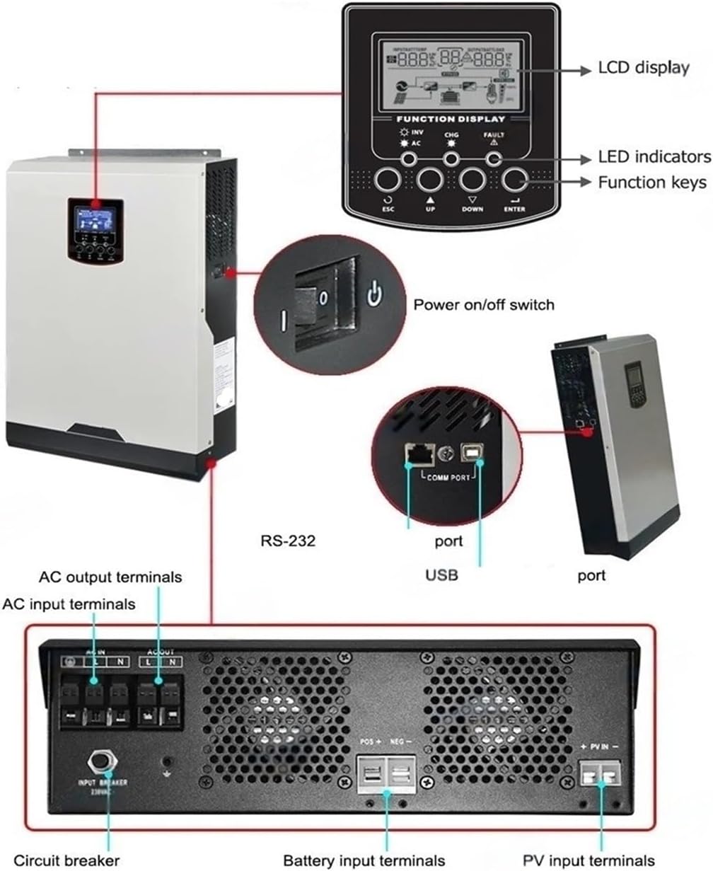
Figure 3.1: Front and rear panel components of the inverter.
Front Panel:
- LCD Display: Shows operational status, parameters, and error codes.
- LED Indicators: Provide quick status updates (e.g., charging, inverter active, fault).
- Function Keys (ESC, UP, DOWN, ENTER): Used for navigating menus and setting parameters on the LCD.
- Power On/Off Switch: Controls the main power to the inverter.
Rear Panel:
- AC Input Terminals: For connecting to the utility grid or generator.
- AC Output Terminals: For connecting to loads.
- Battery Input Terminals: For connecting to the battery bank (if used).
- PV Input Terminals: For connecting to the solar panel array.
- Circuit Breaker: Provides overcurrent protection for the AC input.
- RS-232 Port: For communication with a computer or monitoring system.
- USB Port: For communication or data logging.

Figure 3.2: Detailed view of the inverter's rear connection panel.
4. Setup and Installation
Proper installation is crucial for the safe and efficient operation of your inverter. Follow these steps carefully.
4.1 Site Selection
- Install the inverter indoors, away from direct sunlight, rain, and moisture.
- Ensure the ambient temperature is between 0°C and 55°C (32°F and 131°F).
- Maintain at least 20 cm (8 inches) clearance around the inverter for proper airflow and cooling.
- Mount the inverter vertically on a sturdy wall capable of supporting its weight.
4.2 Wiring Connections
WARNING: Ensure all power sources are disconnected before making any wiring connections. Use appropriate wire gauges for all connections.
- Battery Connection (Optional): If using batteries, connect the 48V battery bank to the Battery Input Terminals (POS+ and NEG-). Ensure correct polarity.
- PV Array Connection: Connect the solar panel array to the PV Input Terminals (+PV IN -). Verify that the maximum open circuit voltage of the PV array does not exceed 500V.
- AC Input Connection: Connect the utility grid or generator to the AC Input Terminals (AC IN L, N). Ensure the input voltage is within the specified range of 90-280VAC.
- AC Output Connection: Connect your loads to the AC Output Terminals (AC OUT L, N).
- Grounding: Connect the inverter's ground terminal to a reliable earth ground.
- Communication Ports: Connect RS-232 or USB cables for monitoring if desired.
5. Operating Instructions
Once all connections are secure, you can power on and operate the inverter.
5.1 Powering On the Inverter
- Ensure all external circuit breakers (PV, battery, AC input) are in the OFF position.
- If using a battery, switch on the battery breaker first.
- Switch on the PV array breaker.
- Switch on the AC input breaker.
- Press the Power On/Off switch on the inverter's front panel to the 'ON' position.
- The LCD display will illuminate, and the inverter will begin its startup sequence.
5.2 LCD Display and Settings
The LCD display provides real-time operational data and allows for configuration of various parameters. Use the Function Keys (ESC, UP, DOWN, ENTER) to navigate through menus and adjust settings.
- ESC: Exits the current menu or returns to the previous screen.
- UP/DOWN: Navigates through menu options or increases/decreases values.
- ENTER: Confirms selection or enters a submenu.
Refer to the detailed user manual (separate document) for specific menu structures and parameter settings, including battery type, charging current, and output priority.
5.3 Powering Off the Inverter
- Disconnect all loads from the AC output.
- Press the Power On/Off switch on the inverter's front panel to the 'OFF' position.
- Switch off the AC input breaker.
- Switch off the PV array breaker.
- If using a battery, switch off the battery breaker.
6. Maintenance
Regular maintenance ensures the longevity and optimal performance of your inverter.
- Cleaning: Periodically clean the inverter's exterior with a dry cloth. Ensure ventilation openings are free from dust and debris. Do not use liquid cleaners.
- Connection Checks: Annually inspect all wiring connections for tightness and signs of corrosion. Re-tighten if necessary.
- Ventilation: Ensure the cooling fan operates correctly and is not obstructed. The inverter features a temperature-controlled cooling fan to prevent overheating.
- Environmental Check: Verify that the installation environment remains within the specified temperature and humidity ranges.
7. Troubleshooting
This section provides guidance for common issues. For complex problems, contact technical support.
| Problem | Possible Cause | Solution |
|---|---|---|
| Inverter does not power on | No input power (AC, PV, Battery) Power switch off Internal fuse blown | Check all breakers and connections. Ensure power switch is ON. Contact service for fuse replacement. |
| No AC output | Overload Short circuit High/low voltage fault Inverter in fault mode | Reduce connected load. Check for short circuits in wiring. Verify input voltage is within range. Check LCD for error codes and refer to manual. |
| Battery not charging | PV input too low/high Battery reverse connection Battery fault | Check PV array voltage and current. Verify battery polarity. Check battery health. |
| Overload warning/shutdown | Connected load exceeds inverter capacity | Reduce the total power consumption of connected devices. |
| High temperature warning | Insufficient ventilation Blocked cooling fan | Ensure adequate clearance around the inverter. Clean any dust or obstructions from the fan and vents. |
8. Specifications
Technical specifications for the LVSEDTAL MPPT Solar Hybrid Inverter 5KW (Model: MPS-V-5500W-PLUS).
| Parameter | Value |
|---|---|
| Model Number | MPS-V-5500W-PLUS |
| Input Voltage | 90-280VAC |
| Output Voltage | 230VAC ± 5% |
| Output Current | 16A |
| Output Frequency | 50Hz/60Hz (Auto sensing) |
| Output Type | Single |
| Solar Controller Type | MPPT 100A |
| Surge Power (5 seconds) | 11000VA |
| Efficiency | 93% |
| Waveform | Pure Sine Wave |
| Battery Voltage | 48V |
| Max PV Array Power | 5500W |
| Maximum PV Array Open Circuit Voltage | 500V |
| Dimensions (L*W*H) | 100*300*440 mm |
| Weight | 9 kg |
9. Warranty and Support
Information regarding product warranty and technical support was not provided in the available data. For details on warranty coverage, terms, and conditions, please refer to the documentation included with your product or contact LVSEDTAL customer service directly.
When contacting support, please have your product model number (MPS-V-5500W-PLUS) and purchase information readily available.