1. Introduction
This manual provides essential information for the proper use and operation of the E28-2G4T12S LoRa Module. The E28-2G4T12S is a 2.4G LoRa spread spectrum serial port module featuring the SX1281 chip and RSSI functionality, designed for various wireless communication applications.
Please read this manual thoroughly before operating the module to ensure optimal performance and longevity.
2. Product Overview

Figure 1: Front view of the E28-2G4T12S LoRa module, showing the metallic shield and integrated antenna.
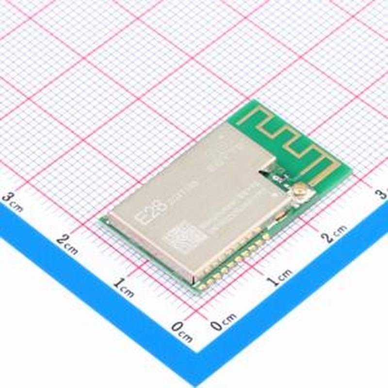
Figure 2: Angled view of the E28-2G4T12S LoRa module, illustrating its compact size of approximately 17.5x28.7mm against a measurement grid.
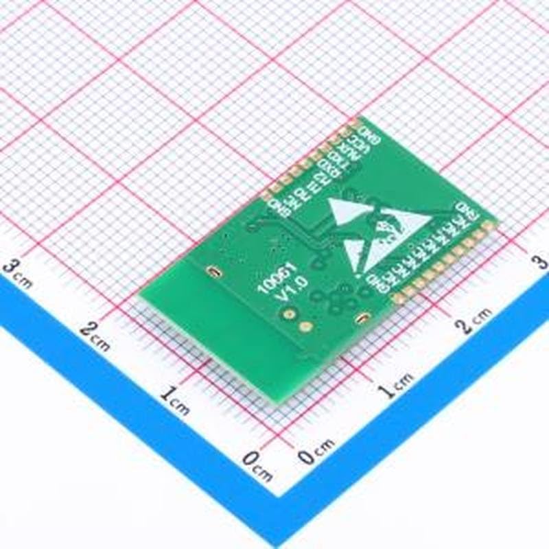
Figure 3: Back view of the E28-2G4T12S LoRa module, displaying the solder pads and pinout labels for integration.
3. Setup
The E28-2G4T12S module is designed for SMD (Surface Mount Device) integration. Proper soldering techniques are crucial for reliable operation.
3.1 Pin Definitions
Refer to Figure 3 for the physical layout of the pins. The module typically includes pins for VCC (power supply), GND (ground), TXD (transmit data), RXD (receive data), and potentially auxiliary pins for configuration or control.
3.2 Power Supply
Ensure the module is supplied with the correct voltage as specified in the technical specifications. Incorrect voltage can damage the module.
3.3 Serial Communication
Connect the module's TXD and RXD pins to the corresponding RXD and TXD pins of your microcontroller or host device. Ensure the baud rate and other serial port parameters are correctly configured on both ends.
4. Operating Instructions
The E28-2G4T12S operates as a serial port module, allowing for easy integration into existing systems via UART communication.
4.1 Data Transmission and Reception
Data is sent to the module via its RXD pin and received from its TXD pin. The module handles the LoRa spread spectrum modulation and demodulation internally.
4.2 RSSI Functionality
The module supports RSSI (Received Signal Strength Indicator) functionality, which can be used to assess the quality of the received signal. Consult the module's datasheet for specific commands or methods to access RSSI values.
4.3 Frequency Band
This module operates in the 2.4GHz frequency band, suitable for global use, but always verify local regulations for wireless device operation.
5. Maintenance
The E28-2G4T12S LoRa module is a robust electronic component, but proper handling and storage are essential for its longevity.
- Handling: Avoid touching the module's pins or antenna area unnecessarily. Use anti-static precautions when handling.
- Storage: Store the module in a dry, cool environment, away from direct sunlight and extreme temperatures. Keep it in its original anti-static packaging if not immediately used.
- Cleaning: If necessary, gently clean the module with a soft, dry, lint-free cloth. Do not use liquid cleaners or solvents.
6. Troubleshooting
If you encounter issues with your E28-2G4T12S module, consider the following common troubleshooting steps:
- No Communication:
- Verify power supply voltage and connections.
- Check serial port connections (TXD to RXD, RXD to TXD).
- Confirm baud rate and serial port settings match on both the module and host device.
- Ensure the module is correctly soldered to the PCB.
- Poor Range/Signal:
- Check for obstructions between modules (e.g., walls, metal objects).
- Ensure the integrated antenna is not obstructed or damaged.
- Verify that both transmitting and receiving modules are operating on the same frequency and parameters.
- Module Not Responding:
- Perform a power cycle (turn off and on).
- Check for short circuits or incorrect wiring.
7. Specifications
| Feature | Description |
|---|---|
| Model | E28-2G4T12S |
| Frequency Band | 2.4 GHz (LoRa Spread Spectrum) |
| Chipset | SX1281 |
| Interface | Serial Port (UART) |
| Functionality | RSSI (Received Signal Strength Indicator) |
| Form Factor | SMD (Surface Mount Device) |
| Dimensions | 17.5mm x 28.7mm |