1. Introduction
The HotTopStar USB-C PD Trigger Board Module is a versatile device designed to negotiate specific voltage outputs from USB-C Power Delivery (PD) and Quick Charge (QC) compatible power sources. This module allows users to select desired voltages (5V, 9V, 12V, 15V, 20V) for various electronic projects and applications, supporting up to 100W power output. It incorporates essential safety features such as over-temperature and over-voltage protection to ensure reliable operation.
2. Product Overview
This module acts as a decoy, requesting a specific voltage from a compatible USB-C power adapter. It is not a boost or buck converter; it only triggers the power source to output the selected voltage.
Key Features:
- Supports PD3.0/2.0 and BC1.2 fast charging protocols.
- Maximum power output of 100W.
- Integrated over-temperature and over-voltage protection.
- Adjustable output voltage from 5V to 20V via DIP switches.
- Supports USB Type-C PD with forward and reverse plug detection.
- Input voltage range: 4V to 22V.
Components:
The module consists of a USB-C input port, a set of three DIP switches for voltage selection, and screw terminals for power output.
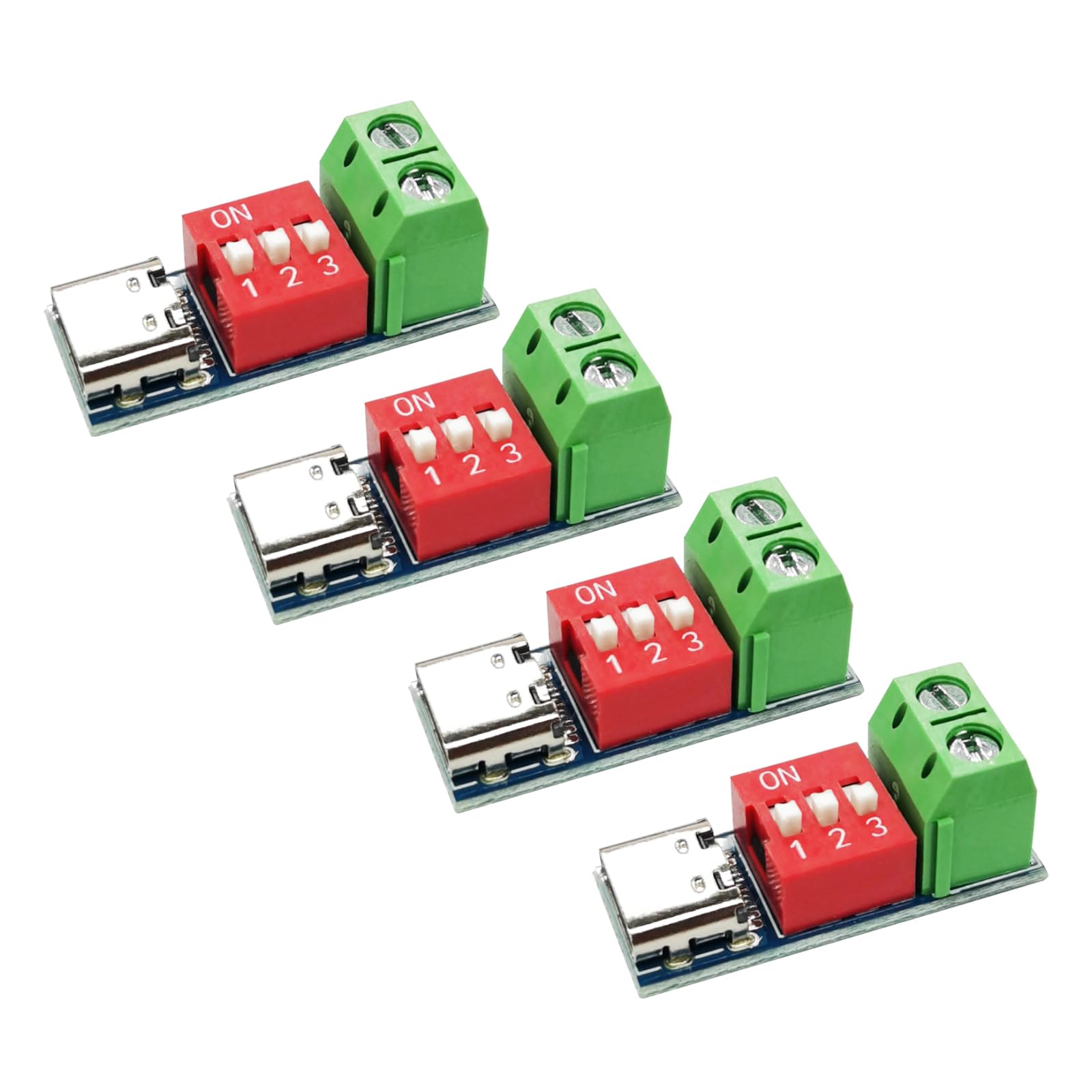
Image: Overview of the HotTopStar USB-C PD Trigger Board Module, highlighting its main components: the USB-C input, the red DIP switches for voltage selection, and the green screw terminals for power output.

Image: Detailed view of the module's components, showing the USB-C connector, the three-position DIP switch, and the two screw terminals for connecting the load.
3. Specifications
| Brand | HotTopStar |
| Model Number | HT-443 |
| Input Voltage | 4V to 22V |
| Output Voltage | Selectable: 5V, 9V, 12V, 15V, 20V |
| Maximum Power Output | 100W |
| Interface | USB Type-C PD |
| Supported Protocols | PD3.0/2.0, BC1.2 |
| Weight | 3.4g (approx. 0.01 Kilograms) |
| Dimensions (L x W x H) | 28mm x 11mm x 12mm (1.1 x 0.43 x 0.47 inches) |

Image: Diagram illustrating the physical dimensions of the USB-C PD Trigger Board Module, showing its length of 28mm (1.10 inches) and width of 11mm (0.43 inches).

Image: A graphic displaying key product parameters including product name, input voltage range, power capacity, weight, output voltage range, interface type, and product size.
4. Setup
- Identify Components: Locate the USB-C input port, the three DIP switches, and the green screw terminals for output.
- Select Desired Voltage: Before connecting power, configure the DIP switches according to the voltage selection table in Section 5. Ensure the switches are firmly set to the 'ON' (top) or 'OFF' (bottom) position.
- Connect Load: Connect your device or circuit requiring power to the green screw terminals. Ensure correct polarity (VBUS and GND).
- Connect Power Source: Plug a compatible USB-C Power Delivery (PD) or Quick Charge (QC) fast charger into the USB-C input port of the module.
Important Note: The mobile phone charger or power source must support fast charging protocols (PD/QC) to output voltages higher than 5V. If the power source does not support the requested voltage, it will default to 5V.
5. Operating Instructions: Voltage Selection
The output voltage of the module is determined by the configuration of the three DIP switches. Each switch corresponds to a configuration bit (CFG1, CFG2, CFG3). Toggle the switch to the bottom for a '0' state and to the top (marked 'ON') for a '1' state.
Voltage Selection Table:
| CFG1 (Switch 1) | CFG2 (Switch 2) | CFG3 (Switch 3) | Requested Voltage |
|---|---|---|---|
| 0 (Bottom) | 0 (Bottom) | 0 (Bottom) | 5V |
| 1 (Top) | 1 (Top) | 1 (Top) | 9V |
| 1 (Top) | 1 (Top) | 0 (Bottom) | 12V |
| 1 (Top) | 0 (Bottom) | 0 (Bottom) | 15V |
| 1 (Top) | 0 (Bottom) | 1 (Top) | 20V |

Image: A visual representation of the DIP switches and their corresponding CFG (Configuration) settings, along with a table detailing how to set the switches to request specific voltages (5V, 9V, 12V, 15V, 20V).
6. Maintenance
- Cleaning: Keep the module clean and free from dust and debris. Use a soft, dry cloth for cleaning. Avoid using liquids or harsh chemicals.
- Storage: Store the module in a dry environment, away from extreme temperatures and moisture, when not in use.
- Inspection: Periodically inspect the USB-C port and screw terminals for any signs of damage or corrosion. Ensure all connections are secure.
7. Troubleshooting
No Output Voltage:
- Check Power Source: Ensure your USB-C power adapter supports Power Delivery (PD) or Quick Charge (QC) protocols. Standard USB chargers may only provide 5V.
- Verify DIP Switch Settings: Double-check that the DIP switches are set correctly according to the voltage selection table for the desired voltage.
- Secure Connections: Ensure the USB-C cable is fully inserted and the wires connected to the screw terminals are secure and have good contact.
- Power Source Capacity: Confirm that your power source can supply the requested voltage and current.
Incorrect Output Voltage:
- Re-check DIP Switches: Carefully review the DIP switch positions against the voltage selection table. A single incorrect switch can lead to an unexpected voltage.
- Power Source Compatibility: If the power source does not support the requested voltage, it will often default to a lower, supported voltage (e.g., 5V). Try a different, known-compatible PD/QC power adapter.
Module Overheating:
- Check Load: Ensure the connected load does not exceed the module's maximum power rating (100W) or the power source's capacity.
- Ventilation: Ensure the module has adequate airflow and is not enclosed in a way that prevents heat dissipation.
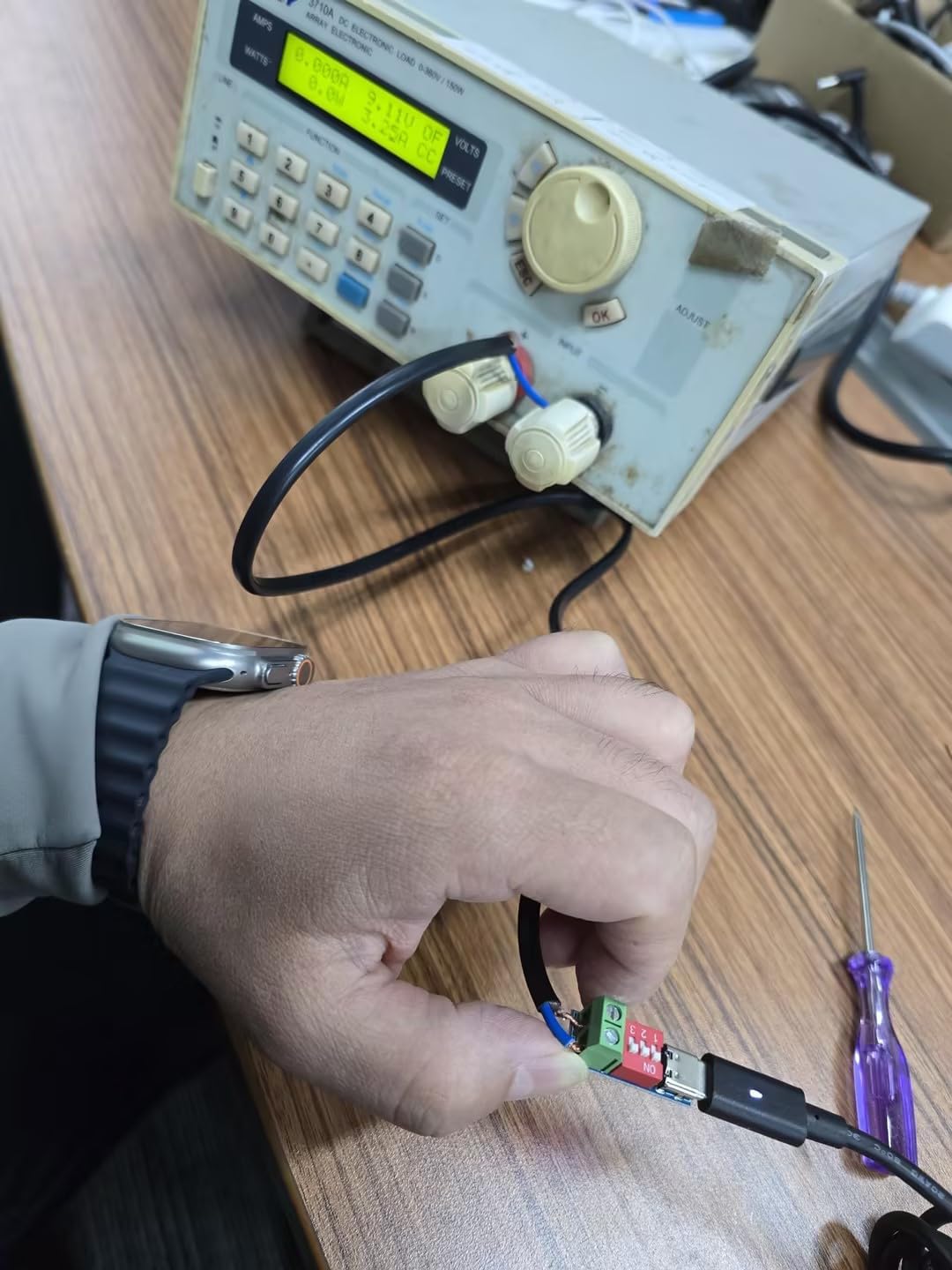
Image: A HotTopStar USB-C PD Trigger Board Module connected to a power supply and measurement equipment, demonstrating a typical testing setup to verify voltage output.
8. Warranty Information
This HotTopStar USB-C PD Trigger Board Module (Model HT-443) comes with a 12-month warranty from the date of purchase. This warranty covers manufacturing defects and malfunctions under normal use. It does not cover damage caused by misuse, accidents, unauthorized modifications, or improper installation.
9. Support
For technical assistance, troubleshooting, or warranty claims, please contact your retailer or the manufacturer directly. When contacting support, please provide your product model number (HT-443) and a detailed description of the issue.