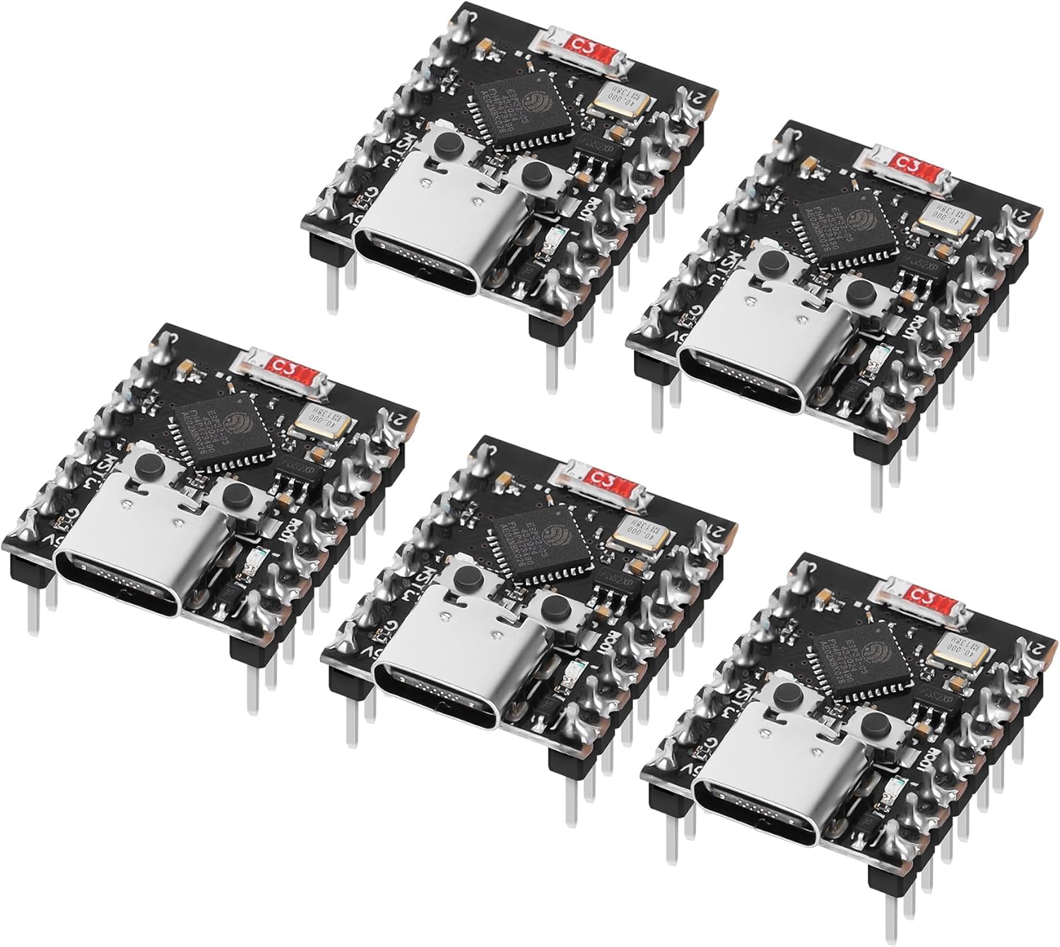
Figure 0: A set of five FancyWhoop ESP32-C3 Supermini Development Boards, showcasing their compact size and USB Type-C interface.
1. Introduction
This user manual provides comprehensive instructions for the FancyWhoop ESP32-C3 Supermini Development Board. This compact board integrates Wi-Fi and Bluetooth 5.0 capabilities, making it suitable for a wide range of Internet of Things (IoT) applications, embedded systems, and educational projects. It features a 32-bit RISC-V single-core processor and pre-soldered pins for ease of use. Please read this manual thoroughly before operating the device.
2. Product Overview
The FancyWhoop ESP32-C3 Supermini is designed for versatility and low-power consumption. Key features include:
- Powerful CPU: ESP32-C3 WiFi/Bluetooth dual-mode chip with a 32-bit RISC-V single-core processor, operating up to 160MHz.
- Rich Interfaces: 11 digital I/Os (PWM), 4 analog I/Os (ADC), 1x I2C, 1x SPI, 2x UART, 11x GPIO.
- Ultra-Low Power Consumption: Deep sleep power consumption approximately 43 µA, ideal for battery-powered applications.
- Excellent RF Performance: Supports IEEE 802.11 b/g/n Wi-Fi and Bluetooth 5 (LE) protocols with an external antenna for enhanced signal strength.
- Reliable Security Features: Built-in 4MB flash, 400KB SRAM, 384KB ROM, supporting AES-128/256, hash, RSA, HMAC, Digital signature, and secure boot encryption hardware acceleration.
- Compact Design: Supermini form factor with pre-soldered pins for easy integration.
2.1. Component Identification

Figure 1: Overview of the ESP32-C3 Supermini Development Board, highlighting key components such as the ESP32-C3 chip, USB Type-C port, BOOT button, RST (Reset) button, and LED GPIO8.
2.2. Pinout Diagram

Figure 2: Detailed pinout diagram for the ESP32-C3 Supermini, showing power pins (5V, GND, 3.3V), GPIO pins (GPIO0-GPIO21), and communication interfaces (UART, I2C, SPI, ADC).
2.3. Physical Dimensions

Figure 3: Physical dimensions of the ESP32-C3 Supermini Development Board, measuring approximately 23mm (0.9in) by 18mm (0.7in) with a height of 9mm (0.35in).
2.4. Pre-Soldered Pins
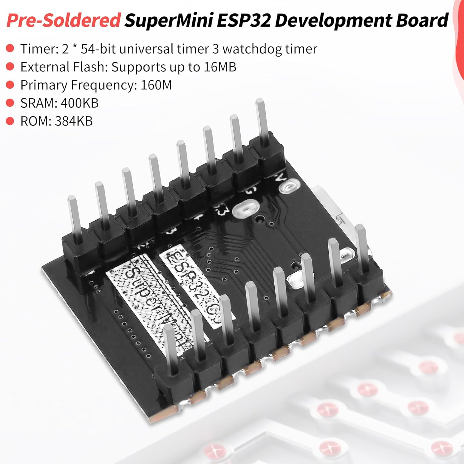
Figure 4: View of the ESP32-C3 Supermini Development Board showcasing its pre-soldered header pins, simplifying integration into breadboards or custom PCBs.
2.5. Schematic Diagram

Figure 5: Detailed schematic diagram of the ESP32-C3 Supermini Development Board, illustrating component connections and circuit layout.
3. Specifications
| Feature | Detail |
|---|---|
| Processor | ESP32-C3 (32-bit RISC-V single-core) |
| CPU Speed | Up to 160 MHz |
| Wireless Connectivity | 2.4 GHz Wi-Fi (802.11 b/g/n), Bluetooth 5 (LE) |
| Memory | 400KB SRAM, 384KB ROM, 4MB Flash |
| Interfaces | 11x Digital I/O (PWM), 4x Analog I/O (ADC), 1x I2C, 1x SPI, 2x UART, USB Type-C |
| Operating Voltage | 3.3V (via USB Type-C or 5V pin) |
| Low Power Consumption | Deep sleep current approx. 43 µA |
| Operating System Support | FreeRTOS, Linux (via Espressif SDKs) |
| Dimensions | Approx. 23mm x 18mm x 9mm |
| Weight | Approx. 0.634 ounces |
4. Setup Guide
To begin using your FancyWhoop ESP32-C3 Supermini Development Board, follow these steps:
- Software Installation:
- Install the Arduino IDE or PlatformIO for VS Code.
- Add the ESP32 board manager URL to your IDE preferences. For Arduino IDE, navigate to File > Preferences and add
https://raw.githubusercontent.com/espressif/arduino-esp32/gh-pages/package_esp32_index.jsonto "Additional Board Manager URLs". - Install the ESP32 boards package via the Board Manager (Tools > Board > Boards Manager). Search for "ESP32" and install the latest version.
- Install necessary USB-to-Serial drivers if your operating system does not automatically recognize the board. The ESP32-C3 typically uses a built-in USB-to-Serial converter, but specific drivers might be needed for some systems.
- Hardware Connection:
- Connect the ESP32-C3 Supermini to your computer using a USB Type-C cable.
- Ensure the cable supports data transfer, not just charging.
- The board should power on, indicated by a power LED (if present).
- IDE Configuration:
- In the Arduino IDE, select the correct board: Tools > Board > ESP32 Arduino > ESP32C3 Dev Module.
- Select the appropriate COM port (Tools > Port) that corresponds to your connected ESP32-C3 board.
5. Operating Instructions
Once your development environment is set up, you can upload and run programs on the ESP32-C3 Supermini.
- Uploading Code:
- Write your code (sketch) in the Arduino IDE or PlatformIO.
- To upload, press and hold the BOOT button on the ESP32-C3 board, then press the RST button. Release the RST button, then release the BOOT button. This puts the board into bootloader mode.
- Click the "Upload" button in your IDE. The IDE will compile and transfer the code to the board.
- After successful upload, the board will automatically reset and run the new program.
- Serial Monitor:
- Open the Serial Monitor in your IDE (Tools > Serial Monitor).
- Set the baud rate to match the one specified in your code (e.g., 115200 baud).
- You can view output from your program and send input to the board via the Serial Monitor.
- Basic Example (Blink LED):
- A common first program is to blink an LED. The ESP32-C3 Supermini has an onboard LED connected to GPIO8.
- You can find example sketches under File > Examples > 01.Basics > Blink in the Arduino IDE, or specific ESP32 examples under File > Examples > ESP32.
6. Maintenance
Proper care ensures the longevity and reliable operation of your development board.
- Handling: Always handle the board by its edges to avoid touching components, especially the pins, which can be sensitive to static discharge.
- Storage: Store the board in an anti-static bag when not in use. Keep it in a dry environment, away from extreme temperatures and direct sunlight.
- Cleaning: If necessary, gently clean the board with a soft, dry brush or compressed air to remove dust. Avoid using liquids or abrasive materials.
- Power Supply: Ensure you use a stable 5V power supply via the USB Type-C port or the 5V pin. Incorrect voltage can damage the board.
- Connections: Double-check all wiring before powering on the board to prevent short circuits or incorrect voltage application to components.
7. Troubleshooting
This section addresses common issues you might encounter.
- Issue: Board not recognized by computer / Upload failed.
- Check USB Cable: Ensure the USB Type-C cable is data-capable and not just for charging.
- Driver Installation: Verify that the necessary USB-to-Serial drivers are installed for your operating system.
- Correct Port Selection: In your IDE, confirm that the correct COM port is selected.
- Bootloader Mode: Ensure the board is correctly put into bootloader mode by holding BOOT, pressing RST, then releasing RST, then releasing BOOT before uploading.
- IDE Board Selection: Confirm "ESP32C3 Dev Module" is selected in your IDE.
- Issue: Code uploads but does not run or behaves unexpectedly.
- Serial Monitor Output: Use the Serial Monitor to check for any error messages or unexpected output from your code. Ensure the baud rate matches.
- Power Supply: Insufficient power can cause erratic behavior. Ensure a stable 5V supply.
- Code Logic: Review your code for logical errors. Test with simple example sketches first.
- Pin Assignments: Verify that GPIO pins are correctly assigned in your code according to the pinout diagram.
- Issue: Wi-Fi or Bluetooth connectivity problems.
- Antenna: Ensure the external antenna is properly connected and not obstructed.
- Code Configuration: Double-check Wi-Fi SSID, password, and Bluetooth pairing procedures in your code.
- Signal Strength: Test the board closer to your Wi-Fi router or Bluetooth device.
8. Warranty and Support
For specific warranty information, please refer to the product's purchase documentation or contact the retailer directly. For technical support, resources are available through the Espressif Systems documentation for the ESP32-C3 chip, as well as community forums for Arduino and ESP32 development.
You can often find solutions and assistance from the active open-source community:


