1. Introduction
This manual provides detailed instructions for the installation, operation, and maintenance of the TGPKPGTCTA SDM120CTM Single Phase Energy Meter. The SDM120CTM is designed for measuring active energy in single-phase electrical systems, featuring RS485 Modbus communication for integration into monitoring systems. Please read this manual thoroughly before installation and operation to ensure safe and correct usage.
2. Product Overview
Key Features
- Compact Size: Designed for space-saving installation.
- Easy Installation: Simple setup process.
- Versatility: Capable of measuring a wide range of energy parameters.
- Low Maintenance: Engineered for reduced wear and tear, ensuring long-term reliability.
- Sensitive Response: Provides accurate readings without mechanical inertia.
3. Technical Specifications
| Specification | Value |
|---|---|
| Output Voltage | 220V |
| Measuring Energy Range | 0 to 99999.9 kWh |
| Phase | Single Phase |
| Max Operating Current | 150A & Above (via CT) |
| Rated Voltage | 230V AC |
| Voltage Range | 176~276V AC |
| Primary Current (CT) | 1-9999A |
| Secondary Input (CT) | 5A |
| Power Consumption | Less than 2W / 10VA |
| Package Dimensions | 1.18 x 0.79 x 0.39 inches |
| Item Weight | 1.1 pounds |
| Manufacturer | TGPKPGTCTA |
| Assembly Required | No |
| Batteries Required | No |
Input & Output Details

This image displays a table outlining the input and output electrical characteristics of the SDM120CTM meter. It specifies the current transformer (CT) primary and secondary current ranges, as well as the rated and operational voltage ranges.
4. Setup and Installation
Safety Precautions
- Ensure all power is disconnected before installation or wiring.
- Installation should only be performed by qualified personnel.
- Follow all local electrical codes and regulations.
- Do not operate the meter if it appears damaged.
Mounting
The SDM120CTM is designed for DIN rail mounting. Securely attach the meter to a standard 35mm DIN rail in an appropriate electrical enclosure. Ensure adequate ventilation around the meter.
Wiring Diagram and Dimensions
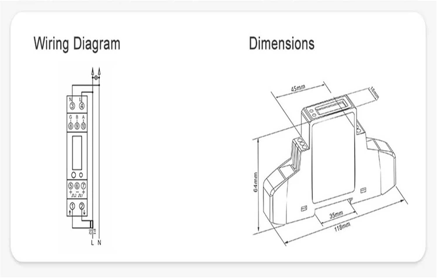
This image provides a detailed wiring diagram for connecting the SDM120CTM energy meter, including voltage inputs, current transformer connections, and RS485 communication terminals. It also includes a dimensional drawing of the meter, showing its length, width, and height in millimeters for installation planning.
Connect the voltage input, current transformer (CT) primary and secondary, and RS485 communication lines according to the diagram. Pay close attention to polarity and terminal designations to prevent damage and ensure accurate readings.
5. Operating Instructions
Display Overview

This image shows the front panel of the SDM120CTM energy meter, highlighting its digital display which indicates energy consumption in kilowatt-hours (kWh). A circular button is visible, used for navigating through various measurement parameters, and an LED provides status indication.
Upon power-up, the meter will display the total active energy (kWh). Use the front panel button (often marked with a circular arrow or similar symbol) to cycle through various measurement parameters such as voltage, current, power, frequency, and power factor. Refer to the specific display sequence in the full technical datasheet for detailed parameter identification.
Modbus Communication (RS485)
The SDM120CTM supports RS485 Modbus RTU protocol for remote data acquisition. Connect the A and B terminals of the meter to your Modbus master device. Ensure correct baud rate, parity, and slave ID settings are configured on both the meter (if adjustable) and the master device for proper communication. Consult the Modbus protocol document for register addresses and data formats.
6. Maintenance
The SDM120CTM energy meter is designed for low maintenance. Regular maintenance includes:
- Cleaning: Periodically wipe the meter's exterior with a soft, dry cloth. Do not use abrasive cleaners or solvents.
- Inspection: Annually inspect wiring connections for tightness and signs of corrosion or damage.
- Environment: Ensure the operating environment remains within specified temperature and humidity ranges.
7. Troubleshooting
If the meter is not functioning as expected, consider the following:
- No Display: Check power supply connections and ensure the voltage is within the operational range.
- Incorrect Readings: Verify CT wiring polarity and ratio settings. Ensure voltage connections are correct.
- No Modbus Communication: Check RS485 wiring (A/B polarity), baud rate, parity, and slave ID settings. Ensure termination resistors are correctly applied if necessary.
- Meter Not Responding: Disconnect power, wait 30 seconds, and reconnect. If the issue persists, contact support.
8. Warranty and Support
For warranty information, technical support, or service inquiries, please contact your retailer or the manufacturer directly. Keep your purchase receipt as proof of purchase.