1. Introduction
This manual provides detailed instructions for the safe installation, operation, and maintenance of your L6AS0F7 CSSGO-06 Swing Gate Opener. Please read this manual thoroughly before installation and keep it for future reference.
1.1 Safety Information
- Ensure all electrical connections are performed by a qualified electrician and comply with local regulations.
- Disconnect power before performing any maintenance or repairs.
- Keep children and pets away from the gate area during operation.
- Do not attempt to operate the gate if any part is damaged or malfunctioning.
- Install safety sensors (not included) to prevent injury or damage from closing gates.
1.2 Package Contents
Verify that all components listed below are present in your package:
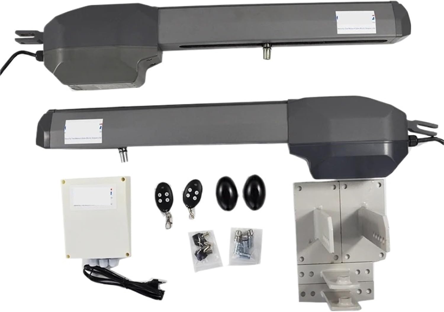
This image displays the full contents of the swing gate opener kit, including the two main gate opener arms, the control box, two remote controls, and various mounting brackets and fasteners required for installation.
- 2 x Swing Gate Opener Arms
- 1 x Control Box
- 2 x Remote Controls
- Mounting Brackets and Hardware
- Keys for Manual Release
- Instruction Manual (this document)
2. Product Overview
2.1 Component Description
Refer to the diagram below for an identification of the main components of the swing gate opener arm.

This diagram illustrates the internal and external components of a single gate opener arm. Key parts include the rear bracket (1), rear fitting (2), release device (3), electric wire (4), aluminum housing (5), arm (6), opening limit switch (7), worm screw (8), long screw (9), pin (10), copperscrew (11), limit switch cover (12), open limit switch (13), front bracket (14), and rear cover (15).
- Rear bracket
- Rear fitting
- Release device
- Electric wire
- Aluminium
- Arm
- Opening limit switch
- Worm screw
- Long screw
- Pin
- Copperscrew
- Limit switch cover
- Open Limit switch
- Front bracket
- Rearcover
2.2 Technical Specifications
| Feature | Specification |
|---|---|
| Model Number | CSSGO-06 |
| Power Input | 230V/120V AC |
| Max Gate Length (Each) | 3 meters (approx. 9.8 feet) |
| Max Gate Weight (Each) | 500 KG (approx. 1100 lbs) |
| Security Mode | Fail Secure |
| Certification | CE |
| Item Weight | 1.76 ounces (Note: This seems to be for a small component, not the full system. Refer to shipping weight for full system.) |
| Assembly Required | Yes (for installation) |
3. Setup and Installation
Proper installation is crucial for the safe and efficient operation of your gate opener. It is recommended that installation be performed by a professional or someone with experience in electrical and mechanical systems.
3.1 Pre-Installation Checks
- Ensure your gate operates smoothly manually and is properly balanced.
- Verify that the gate structure is strong enough to support the opener arms.
- Confirm availability of 230V or 120V AC power supply at the installation site.
3.2 Mounting the Opener Arms
Mount the rear brackets (1) securely to your gate post and the front brackets (14) to the gate frame. Ensure the arms (6) are level and have sufficient clearance for full gate travel. The exact mounting position will depend on your gate's geometry and opening angle.

This image provides a clear view of the two gate opener arms, the control box, remote controls, and the various bolts and brackets that are used for mounting the system to the gate and posts.
3.3 Electrical Wiring
- Connect the electric wires (4) from each opener arm to the control box according to the wiring diagram provided with the control box.
- Connect the main power supply (230V/120V AC) to the control box. Ensure proper grounding.
- Install any optional safety sensors or accessories at this stage.
3.4 Limit Switch Adjustment
The opening limit switch (7) and open limit switch (13) define the gate's fully open and fully closed positions. Adjust these switches carefully to prevent the gate from over-extending or hitting its stops too hard. Refer to the control box manual for specific programming steps.
4. Operating Instructions
Once installed and configured, the gate opener can be operated using the provided remote controls.
4.1 Remote Control Operation
- Press the designated button on the remote control to open or close the gate.
- A second press during operation will typically stop the gate. A third press will reverse its direction.
- Ensure a clear line of sight to the gate and that no obstructions are present before operating.
4.2 Manual Release
In case of power failure or malfunction, the gate can be operated manually. Use the provided key to unlock the release device (3) on each opener arm. This disengages the motor, allowing you to push the gate open or closed by hand. Remember to re-engage the motor after manual operation.
5. Maintenance
Regular maintenance ensures the longevity and reliable operation of your gate opener system.
5.1 Routine Checks (Monthly)
- Inspect all mounting hardware for tightness.
- Check the gate's manual operation for smooth movement and balance.
- Clean any debris from the opener arms and limit switch areas.
- Verify that safety sensors (if installed) are functioning correctly.
5.2 Lubrication (Every 6 Months)
Apply a suitable lubricant to the moving parts of the opener arms, such as the worm screw (8) and pivot points, to reduce friction and wear.
6. Troubleshooting
This section addresses common issues you might encounter with your gate opener.
6.1 Common Issues and Solutions
- Gate does not respond to remote:
- Check power supply to the control box.
- Verify remote control batteries.
- Ensure the manual release is fully engaged.
- Reprogram remote control if necessary (refer to control box manual).
- Gate opens/closes partially:
- Check for obstructions in the gate's path.
- Inspect limit switch settings; they may need adjustment.
- Ensure the gate moves freely manually.
- Gate makes unusual noises:
- Lubricate moving parts as per maintenance schedule.
- Check for loose hardware or worn components.
- Gate reverses unexpectedly:
- Check for obstructions or excessive friction.
- Inspect safety sensors for proper alignment or damage.
7. Warranty and Support
Specific warranty details are typically provided at the point of purchase or within separate documentation from the seller. Please retain your proof of purchase for warranty claims.
7.1 Customer Support
For technical assistance, troubleshooting beyond this manual, or warranty inquiries, please contact the seller or manufacturer directly. Refer to your purchase documentation for contact information.