1. Introduction
This manual provides essential information for the safe and efficient installation, operation, and maintenance of the Lichuan A5 AC Servo Motor Controller Driver Kit. This kit is designed for precision motion control in various industrial applications, particularly CNC machinery.
1.1 Safety Information
- Electrical Hazard: This product operates with high voltage. Installation and maintenance should only be performed by qualified personnel.
- Grounding: Ensure the motor and driver are properly grounded to prevent electric shock.
- Moving Parts: The servo motor contains moving parts. Ensure all safety guards are in place before operation.
- Power Disconnection: Always disconnect power before performing any installation, wiring, or maintenance tasks.
- Environmental Conditions: Operate the device within specified temperature and humidity ranges to prevent damage.
2. Package Contents
Upon unpacking, please verify that all components listed below are present and undamaged. If any items are missing or damaged, contact your supplier immediately.
- Lichuan AC Servo Motor
- Lichuan AC Servo Motor Driver
- Motor Power Cable
- Encoder Cable
- Instruction Manual (this document)
- Accessory Kit (connectors, screws, etc.)

Figure 2.1: Typical Package Contents. The image displays the servo motor, servo driver, various connection cables, and the user manual neatly packed within a product box.
3. Specifications
Key technical specifications for the Lichuan A5 400W Absolute AC Servo Motor Controller Driver Kit:
| Parameter | Value |
|---|---|
| Model | A5 400W Absolute |
| Rated Power | 400W |
| Input Voltage | 220V AC (Single-phase) |
| Rated Speed | 3000 RPM |
| Encoder Type | 17/23-bit Incremental/Absolute Encoder |
| Manufacturer | GIGACOM |
| Part Number | MPGC9708F7C21A48D548B52430CCBA0A622A |
| Date First Available | March 3, 2025 |
4. Setup and Installation
Proper installation is crucial for the performance and longevity of the servo system. Follow these guidelines carefully.
4.1 Pre-Installation Check
Before permanent installation, it is recommended to power on and test the servo motor and driver kit to ensure proper functionality. This helps prevent damage from potential collisions during transportation or initial setup. After confirming normal operation, proceed with mounting the equipment onto your machine.
4.2 Mounting
- Servo Motor: Mount the servo motor securely to the machine frame using appropriate fasteners. Ensure proper alignment with the driven load to avoid excessive stress on the motor shaft.
- Servo Driver: Install the servo driver in a well-ventilated enclosure, away from direct heat sources, excessive dust, and moisture. Allow sufficient clearance for airflow around the driver's heat sinks.
4.3 Wiring Diagram
Refer to the detailed wiring diagram below for connecting the servo motor, driver, power supply, and control signals. Ensure all connections are secure and correctly polarized.

Figure 4.1: Wiring Diagram. This diagram illustrates the connections for the servo driver (LC10L), servo motor, power supply (single-phase 220VAC), encoder wire, brake resistance, HMI, and PLC. It highlights the CN1 and CN2 ports for I/O and communication, and the 485 interface for HMI/PLC communication.
4.3.1 Power Connections
- Connect the single-phase 220V AC power supply to the L and N terminals on the servo driver.
- Connect the Protective Earth (PE) terminal to a reliable ground.
- If using a brake resistance, connect it to the B1, B2, and B3 terminals as shown in the diagram.
4.3.2 Motor Connections
- Connect the motor phase wires (U, V, W) from the servo motor to the corresponding U, V, W terminals on the servo driver.
- Connect the motor's Protective Earth (PE) to the driver's PE terminal.
4.3.3 Encoder Connections
- Connect the encoder cable from the servo motor to the designated encoder port on the servo driver (typically CN2 or a dedicated encoder input).
- Ensure correct pin assignments for Red, White, Black, and Green/Yellow wires as indicated in the diagram.
4.3.4 Control Signal Connections
- CN1: This port is typically used for pulse signal I/O and other control signals. Connect to your CNC controller or PLC.
- CN2: This port may also carry I/O signals or serve as an encoder input depending on the specific driver model.
- 485 Interface: The driver supports RS485 communication for connection to an HMI (Human Machine Interface) or PLC (Programmable Logic Controller) for advanced control and monitoring.
5. Operating Instructions
Once the servo system is correctly installed and wired, follow these steps for initial power-up and operation.
5.1 Initial Power-Up
- Double-check all wiring connections for correctness and security.
- Ensure no foreign objects are near the motor or driver.
- Apply power to the servo driver. The driver's display should illuminate, indicating power-on status.
- Observe the driver's display for any error codes. Refer to the Troubleshooting section if an error is present.
5.2 Basic Operation
- The servo driver receives commands (e.g., position, speed, torque) from an external controller such as a CNC system or PLC via the CN1/CN2 ports or the RS485 interface.
- Use the external controller's software or HMI to send motion commands to the servo system.
- Monitor the motor's movement and the driver's status indicators during operation.
5.3 Parameter Settings
The servo driver has various configurable parameters that can be adjusted to optimize performance for specific applications. These parameters are typically accessed and modified via the driver's built-in display and buttons (M, ▲, ▼, SET) or through the RS485 communication interface using a dedicated software tool or HMI. Refer to the detailed programming manual (if provided separately) for a complete list and explanation of parameters.
6. Maintenance
Regular maintenance helps ensure reliable operation and extends the lifespan of your servo system.
- Cleaning: Periodically clean the servo motor and driver to remove dust and debris. Use a soft, dry cloth. Avoid using solvents or abrasive cleaners. Ensure ventilation openings on the driver are clear.
- Connection Checks: Regularly inspect all electrical connections for tightness and signs of corrosion. Loose connections can lead to intermittent operation or damage.
- Environmental Monitoring: Ensure the operating environment remains within the specified temperature and humidity ranges. Excessive heat or moisture can degrade performance and reliability.
- Cable Inspection: Check motor and encoder cables for any signs of wear, cuts, or damage. Replace damaged cables immediately.
7. Troubleshooting
This section provides guidance for common issues. For complex problems, contact technical support.
| Problem | Possible Cause | Solution |
|---|---|---|
| Driver display off / No power | No input power; Blown fuse; Loose power connection. | Check power supply; Inspect fuses; Verify power cable connections. |
| Motor does not move | Incorrect wiring; No command signal; Driver in error state; Motor brake engaged. | Review wiring diagram; Check control signals from PLC/CNC; Clear driver errors; Verify brake release. |
| Motor vibrates or makes abnormal noise | Improper tuning parameters; Mechanical resonance; Loose motor mounting; Encoder issue. | Adjust servo gain parameters; Check mechanical coupling; Secure motor mounting; Inspect encoder cable. |
| Driver displays error code | Overcurrent, overvoltage, encoder fault, etc. | Refer to the driver's specific error code manual for detailed explanations and solutions. Address the root cause (e.g., reduce load, check power, inspect encoder). |
8. Applications
The Lichuan A5 AC Servo Motor Controller Driver Kit is suitable for a wide range of precision motion control applications in industrial automation, including but not limited to:
- Automated Machines
- Laser Machines
- Robots
- Packaging Machines
- 3D Printers
- CNC Machines
- Engraving Machines
- Textile Machines
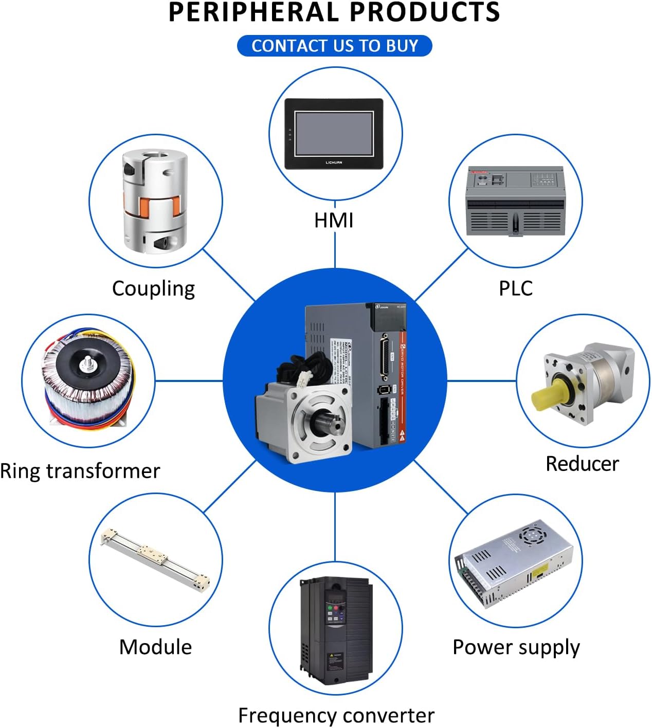
Figure 8.1: Typical Applications. The image illustrates a central servo motor and driver kit surrounded by various industrial machines where it can be utilized, such as CNC machines, robots, and 3D printers.
9. Warranty and Support
For warranty information, technical support, or service inquiries, please contact your original point of purchase or the manufacturer, GIGACOM. Ensure you have your product model number (A5 400W Absolute) and part number (MPGC9708F7C21A48D548B52430CCBA0A622A) available when seeking assistance.