1. Introduction and Overview
The RYRMCVPVCT JK-B2A20S20PHC is a Smart Active Balance Battery Management System (BMS) designed for Li-Ion, LiFePo4, and LTO battery packs. This advanced BMS ensures the safety and longevity of your battery system by actively balancing cell voltages and providing comprehensive protection functions. It supports battery configurations from 8S to 24S and handles charging/discharging currents up to 200A. Key features include integrated heating (H) and CANBUS (C) functionalities, along with Bluetooth connectivity for real-time monitoring and configuration via a dedicated mobile application.
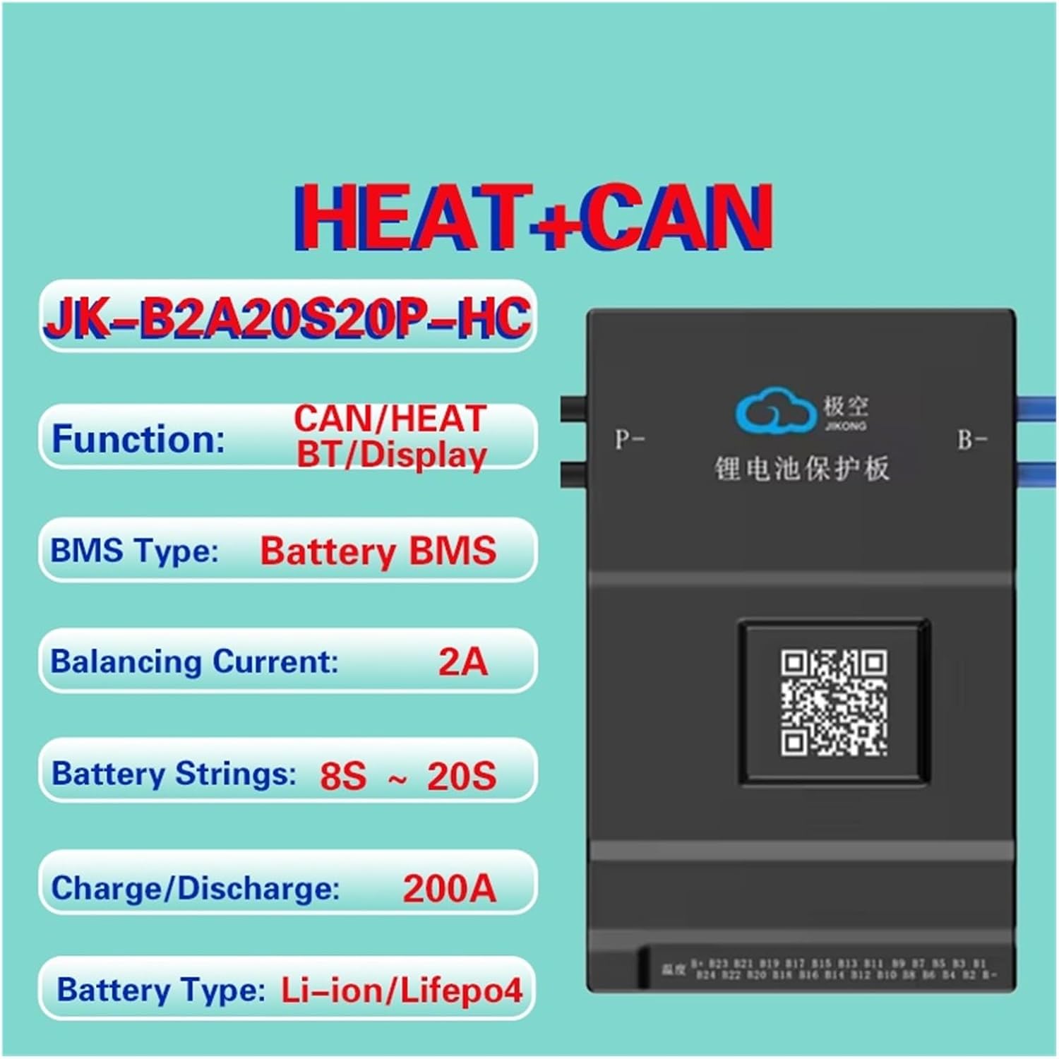
Figure 1: Overview of JK-B2A20S20PHC BMS features, highlighting its CAN/HEAT functions, Bluetooth connectivity, active balancing, and compatibility with various battery types and string counts.
2. Product Features
- Smart Active Balance: The JK BMS actively balances voltage differences between battery cells, significantly increasing battery usage efficiency up to 99% and extending battery life. The equilibrium efficiency is increased by up to 400% compared to passive balancing systems.
- Dedicated Mobile Application: Utilize the JK Own Development APP for detailed BMS settings and real-time monitoring of battery status via Bluetooth communication.
- Comprehensive Protection: Provides robust protection against over-charge, over-discharge, over-current, short circuit, and includes a low-temperature charging cut-off feature.
- CANBUS and Heating Functionality: This specific model (PHC) includes both CANBUS communication and a heating function (H) for enhanced control and performance in various environments.
- Wide Compatibility: Supports a range of battery configurations from 8S to 24S for Li-Ion, LiFePo4, and LTO battery systems, with a 0.6-2A active balance current and up to 200A continuous charge/discharge current.

Figure 2: Illustration of the efficient active balancing mechanism, demonstrating how the JIKONG BMS significantly improves battery equilibrium and prolongs battery life.
3. Setup Instructions
3.1 Unpacking and Inspection
Carefully unpack the BMS and all included components. Verify that all items listed in the packing list are present and undamaged. If any items are missing or damaged, contact your supplier immediately.

Figure 3: Contents of the product package, including the BMS unit, NTC temperature sensor, and two sampling lines.
3.2 Component Identification
Familiarize yourself with the various ports and components of the BMS unit. The BMS features multiple interfaces for communication, temperature sensing, and cell voltage sampling.

Figure 4: Rich interface of the BMS, detailing connection points for various functions and communication protocols.
3.3 Wiring Connections
Proper wiring is crucial for the safe and correct operation of the BMS. Refer to the diagram below and follow these steps:
- Connect B- (Battery Negative): Connect the main negative terminal of your battery pack to the B- port on the BMS.
- Connect P- (Load/Charge Negative): Connect the negative terminal for your load and charger to the P- port on the BMS. This model uses a common port for charge and discharge.
- Connect Sampling Lines: Carefully connect the cell voltage sampling lines (Sampling line A and Sampling line B) to their respective ports on the BMS. Ensure each cell's voltage is connected to the correct pin on the sampling harness. Incorrect connection can damage the BMS or battery.
- Connect NTC (Temperature Sensor): Connect the NTC temperature sensor to the designated NTC port on the BMS. Position the sensor appropriately on the battery pack to monitor temperature.
- Optional Connections: If using, connect CAN/RS485 communication cables, GPS, or display/switch modules to their respective ports.

Figure 5: Internal structure of the BMS, highlighting key components and connection points for sampling lines.
3.4 Initial Power-Up and APP Connection
After all connections are securely made, power up your battery system. Download the JK BMS mobile application from your device's app store. Enable Bluetooth on your mobile device and open the APP to search for and connect to your BMS. Follow the in-app instructions for initial setup and configuration.
4. Operating Instructions
4.1 Monitoring via APP
The JK BMS APP provides a comprehensive interface for monitoring your battery system. You can view real-time data such as:
- Total battery voltage
- Individual cell voltages
- Charge/discharge current
- Battery temperature (via NTC sensor)
- State of Charge (SOC)
- Balancing status
- Protection status and fault codes
4.2 Configuration and Settings
The APP allows you to adjust various parameters to suit your battery type and application. These may include:
- Overcharge and over-discharge voltage thresholds
- Overcurrent limits
- Temperature protection thresholds
- Balancing voltage and current settings
- CANBUS communication parameters (if applicable)
- Heating function activation and settings (if applicable)
Always ensure that any changes made to the BMS settings are compatible with your specific battery chemistry and manufacturer recommendations to prevent damage or safety hazards.
4.3 Protection Functions
The BMS will automatically trigger protection mechanisms if any monitored parameter exceeds its set limits. When a protection event occurs, the BMS may:
- Cut off charging or discharging current.
- Activate the heating function (if enabled and temperature is low).
- Log the fault in the APP.
Consult the APP for details on active protections and clear any fault conditions before resuming normal operation.
5. Maintenance
To ensure optimal performance and longevity of your BMS and battery system, consider the following maintenance practices:
- Regular Inspection: Periodically check all wiring connections for tightness and corrosion. Ensure the BMS unit is securely mounted and free from physical damage.
- Environmental Conditions: Operate the BMS within its specified temperature and humidity ranges. Avoid exposure to direct sunlight, excessive moisture, or corrosive environments.
- Software Updates: Check the JK BMS APP regularly for any available firmware updates for your BMS. Keeping the firmware updated can improve performance and add new features.
- Battery Health Monitoring: Use the APP to monitor individual cell voltages and balancing activity. Consistent cell voltage differences may indicate an issue with the battery pack or BMS.
- Cleaning: Keep the BMS unit clean and free of dust and debris. Use a soft, dry cloth for cleaning. Do not use liquid cleaners.
6. Troubleshooting
This section provides guidance for common issues you might encounter with your JK-B2A20S20PHC BMS.
6.1 BMS Not Powering On / No APP Connection
- Check Main Connections: Ensure the B- and P- terminals are correctly and securely connected to the battery pack and load/charger.
- Verify Cell Voltage Connections: Incorrectly wired sampling lines can prevent the BMS from powering up or communicating. Double-check each cell connection.
- Battery Voltage: Confirm that the battery pack voltage is within the operational range for the BMS (e.g., 8S-24S).
- Bluetooth: Ensure Bluetooth is enabled on your mobile device and the APP has necessary permissions. Try restarting the APP or your phone.
6.2 Battery Not Charging or Discharging
- Check APP for Protections: The BMS may have triggered a protection (e.g., over-discharge, over-current, low temperature). Check the APP for active fault codes.
- Verify Charger/Load: Ensure your charger and load are functioning correctly and connected to the P- terminal.
- Temperature: If the low-temperature charging cut-off is active, the battery will not charge until its temperature rises above the set threshold.
6.3 Cell Voltage Imbalance
- Active Balancing Status: Check the APP to confirm that active balancing is enabled and functioning.
- Battery Health: Significant and persistent imbalance may indicate a problem with one or more battery cells. Consider having the battery pack professionally inspected.
- Sampling Line Integrity: Ensure all sampling lines are securely connected and not damaged, as this can lead to inaccurate voltage readings and poor balancing.
For issues not covered here, or if troubleshooting steps do not resolve the problem, please contact customer support.
7. Specifications
The following table provides detailed technical specifications for the JK-B2A20S20PHC BMS model. Please note that specifications may vary slightly between different models (e.g., JK-B2A20S20P).

Figure 6: Detailed product parameters for JIKONG BMS models, including the JK-B2A20S20PHC.
| Parameter | Value |
|---|---|
| Model | JK-B2A20S20PHC |
| Number of Battery Strings (Li-ion/LiFePo4) | 7S-20S |
| Number of Battery Strings (LTO) | 12S-24S |
| Balance Method | Active Balance (Full State On) |
| Balance Current | 2A |
| Continuous Charge Current | 200A |
| Continuous Discharge Current | 200A |
| Maximum Discharge Current (MAX 300s) | 350A |
| Over Charge Protection Current (Adj) | 10-200A |
| Other Interfaces | CANBUS, HEAT, RS485 |
| Size | 162*102*20mm |
| Single Cell Voltage Range | 1-5V |
| Voltage Acquisition Accuracy | ±5mV |
| Over Charge Protection Voltage | 1.2-4.35V Adjustable |
| Over Discharge Protection Voltage | 1.2-4.35V Adjustable |
| Over Current Detect Delay | 2-120s Adjustable |
| Temperature Detection | 3 Pcs |
| Short Circuit Protection | Yes |
| Coulomb Counter | Yes |
| Bluetooth Function | Support for Android/iOS phone |
| Package Dimensions | 1.18 x 0.79 x 0.39 inches |
| Item Weight | 2.2 pounds |
8. Warranty and Support
For warranty information, please refer to the documentation provided at the time of purchase or contact your seller directly. Warranty terms and conditions may vary.
For technical support, troubleshooting assistance beyond this manual, or inquiries regarding product functionality, please contact the RYRMCVPVCT customer service or your authorized dealer. When contacting support, please have your product model (JK-B2A20S20PHC) and purchase details readily available.