1. Introduction
This manual provides detailed instructions for the installation, operation, and maintenance of your Coiiwsei RTH702 Multi-Stage Thermostat. This non-programmable thermostat is designed for 2 Heat/2 Cool systems, offering clear temperature control for your home's heating and cooling needs. Please read this manual thoroughly before installation and use to ensure proper function and safety.
2. Important Safety Instructions
- Always turn off power to the heating/cooling system at the main fuse or circuit breaker panel before installing or servicing the thermostat.
- Ensure all wiring is performed in accordance with local electrical codes and ordinances.
- If you are unsure about any part of the installation process, it is recommended to consult a qualified HVAC technician.
- Do not use this thermostat with systems that operate on voltages exceeding 30V AC.
- Keep the thermostat away from direct sunlight, heat sources, or drafts, as these can affect temperature readings.
3. Package Contents
Verify that all items listed below are included in your package:
- 1 x Coiiwsei RTH702 Thermostat
- 1 x Wall Plate
- 1 x Instruction Manual
- 1 x Screw Set (screws and wall anchors)
- 1 x Wiring Labels

4. System Compatibility
The Coiiwsei RTH702 thermostat is designed for a wide range of HVAC systems. Please review the compatibility information below to ensure it is suitable for your system.
Compatible Systems:
- Single-stage or Multi-stage systems
- Forced air (gas, oil, or electric)
- Electric furnace
- Hot water steam or gravity radiant heat
- Heat only systems
- Heat pump without auxiliary or emergency heat
- Millivolt systems
- 24V Gas fireplaces
- Floor or wall furnaces
- Cool only systems
Not Compatible With:
- Heat pump with auxiliary or emergency heat
- Dual fuel/hybrid heating systems
- Electric baseboard heat (110-240 volts)
- Line voltage systems
- Convectors
- Radiant-ceiling heat
- Mini split systems
- 12V RV systems

5. Installation Guide
5.1 Tools Required
- Phillips head screwdriver
- Drill (with appropriate bit for wall anchors, if needed)
- Wire strippers (if wires are not pre-stripped)
- Pencil
- Level (optional)
5.2 Removing Your Old Thermostat
- Turn off power: Locate the main fuse or circuit breaker panel and turn off the power to your heating and cooling system.
- Remove old thermostat cover: Carefully remove the cover of your old thermostat.
- Photograph wiring: Take a clear picture of the wiring connections before disconnecting any wires. This will serve as a reference.
- Label wires: Use the provided wiring labels to mark each wire with its corresponding terminal letter (e.g., R, C, W, Y, G).
- Disconnect wires: Loosen the terminal screws and disconnect the wires from your old thermostat.
- Remove old wall plate: Unscrew and remove the old thermostat's wall plate.
5.3 Mounting the New Wall Plate
- Position wall plate: Hold the new Coiiwsei wall plate against the wall where you want to mount it. Ensure it covers any previous paint marks or holes.
- Mark screw holes: Use a pencil to mark the positions for the mounting screws through the holes in the wall plate.
- Drill holes (if needed): If drilling into drywall, use a drill to create pilot holes for the wall anchors. Insert the wall anchors.
- Secure wall plate: Feed the thermostat wires through the opening in the wall plate and then screw the wall plate securely to the wall.
5.4 Wiring the Thermostat
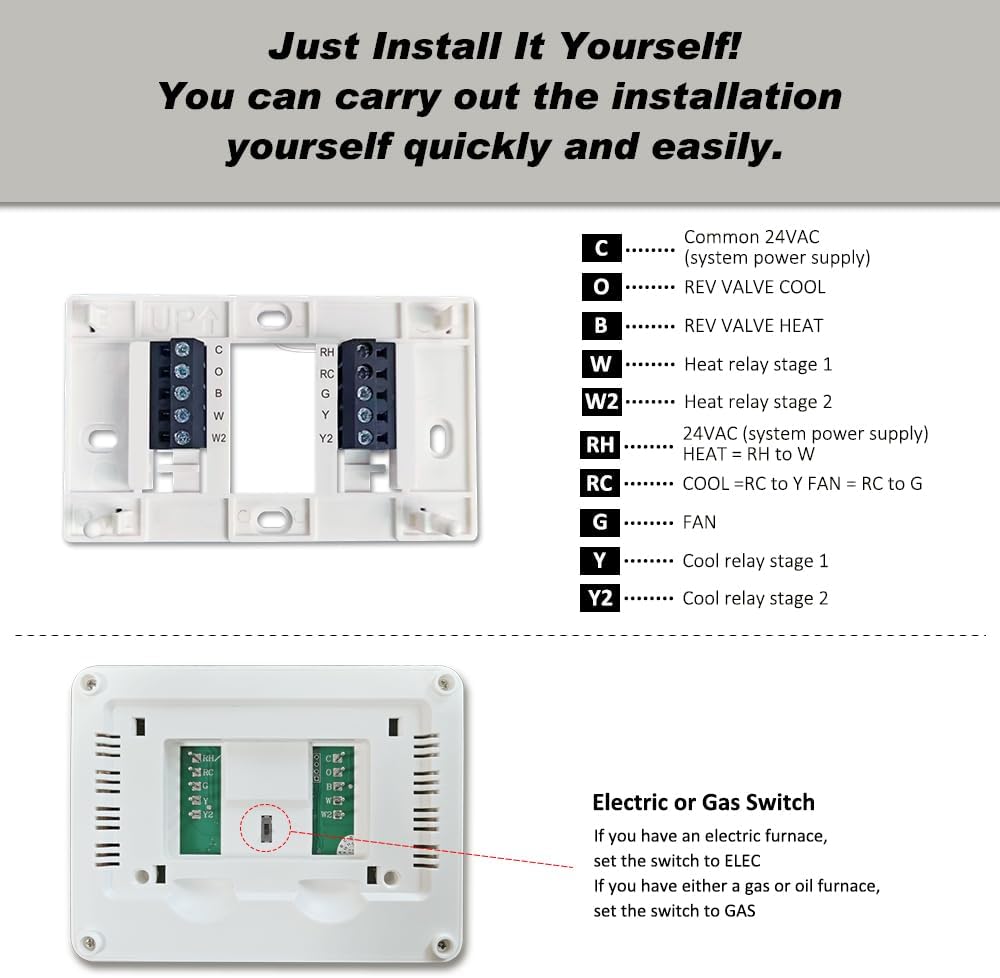
Refer to the wiring diagram below and your previously taken photograph to connect the wires to the new thermostat's terminals. Ensure wires are stripped approximately 3/8 inch (9.5 mm) and inserted firmly into the terminal blocks.

- C: Common 24VAC (system power supply)
- O: Reversing valve cool
- B: Reversing valve heat
- W: Heat relay stage 1
- W2: Heat relay stage 2
- RH: 24VAC (system power supply) - Heat
- RC: 24VAC (system power supply) - Cool
- G: Fan relay
- Y: Cool relay stage 1
- Y2: Cool relay stage 2
Important: If you have both RH and RC wires, remove the metal jumper wire connecting them. If only 2 wires are used, batteries must be installed for operation.
5.5 Attaching the Thermostat Body
Once wiring is complete, align the thermostat body with the wall plate and gently push until it snaps into place.
6. Initial Setup and Configuration
6.1 Battery Installation
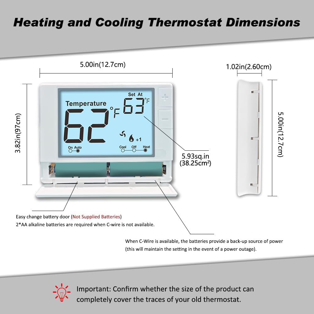
The thermostat requires 2 AA alkaline batteries (not supplied) for operation if a C-wire is not connected, or as a backup power source if a C-wire is present. Open the front-load battery compartment and insert the batteries, observing the correct polarity.
6.2 System Type Selection (Gas/Electric Switch)
On the back of the thermostat's circuit board, locate the small switch labeled
Ask a question about this manual
Ask about setup, troubleshooting, compatibility, parts, safety, or missing instructions. Manuals+ will review the question and use this page’s manual context to help answer it.