1. Product Overview
The QLWAHK Automatic Transfer Switch (ATS) is designed to automatically switch between two power sources, ensuring continuous power supply to your load. This specific model is a 2-pole, 63A, 220V AC switch configured for City Grid to City Grid power transfer, meaning it manages power from two independent utility grid sources. It features both automatic and manual operation modes, with clear indicators for power status and closing.

Figure 1: Front view of the Automatic Transfer Switch, illustrating key components such as the manual operation handle, power indicators, and connection terminals. This diagram helps identify the various parts of the device for proper installation and operation.
2. Safety Instructions
WARNING: Installation and maintenance must be performed by qualified electrical personnel only. Failure to follow these instructions may result in serious injury or death.
- Always disconnect all power sources before installing or servicing the ATS.
- Ensure proper grounding of the device.
- Verify that the voltage and current ratings of the ATS match your application requirements.
- Do not operate the manual handle when the switch is in "AUTO" mode to prevent damage or malfunction.
- Wear appropriate personal protective equipment (PPE) during installation and maintenance.
3. Installation
The ATS is designed for DIN rail mounting within an electrical enclosure. Ensure adequate space for wiring and ventilation.
3.1 Dimensions and Mounting
Refer to the diagram below for precise dimensions and terminal wiring area specifications. The device should be mounted vertically.

Figure 2: Dimensional drawing of the ATS, including overall width, height, and depth. It also specifies the terminal wiring area (1-25mm²) and the screw size (M5) with a recommended torque of 3.0 N.m for secure connections.
3.2 Terminal Connections
The ATS features clearly marked terminals for input power sources (LIL, LIN for Power I; LII, LIIN for Power II) and load output (LOAD). Use appropriate wire gauges for the 63A rating.

Figure 3: Side view of the Automatic Transfer Switch, highlighting the input and output wiring terminals. This view is helpful for understanding the physical layout for wire connections.
4. Wiring Diagram
Connect the primary and secondary power sources, along with the load, according to the diagram below. Ensure all connections are tight and secure to prevent arcing and overheating.
Figure 4: Comprehensive wiring diagram for the ATS, showing connections for Backup Power Live Wire, Backup Power Neutral Wire, Common Power Live Wire, Common Power Neutral Wire, Load Output Live Wire, and Load Output Neutral Wire. It also labels the Backup Closing Indicator, Manual Operation Handle, Common Closing Indicator, Backup Auto/Manual Switch, Backup Power Indicator, Common Power Indicator, and Common Auto/Manual Switch.
- Backup Power (Source II) Connection: Connect the Backup Power Live Wire to terminal LII and Backup Power Neutral Wire to terminal LIIN.
- Common Power (Source I) Connection: Connect the Common Power Live Wire to terminal LIL and Common Power Neutral Wire to terminal LIN.
- Load Output Connection: Connect the Load Output Live Wire to the 'LOAD' live terminal and Load Output Neutral Wire to the 'LOAD' neutral terminal.
- Control Circuit: The internal control circuit manages the automatic transfer based on power availability.
5. Operation
The ATS offers both automatic and manual operation modes.
5.1 Automatic Mode (AUTO)
In "AUTO" mode, the switch automatically detects the availability of power from Source I (Common Power) and Source II (Backup Power). It prioritizes Source I. If Source I fails, the switch will automatically transfer the load to Source II. When Source I is restored, the switch will automatically transfer the load back to Source I after a brief delay.
Important: Do not switch the grey button handle manually while the device is in "AUTO" mode. This can cause damage to the mechanism.
5.2 Manual Mode (MANU)
To operate the switch manually, first switch the mode selector to "MANU". Then, use the manual operation handle to physically switch between Source I and Source II. The indicators will show which source is currently connected to the load.
5.3 Indicators
- Common Power Indicator: Illuminates when Common Power (Source I) is available.
- Backup Power Indicator: Illuminates when Backup Power (Source II) is available.
- Common Closing Indicator: Illuminates when the load is connected to Common Power (Source I).
- Backup Closing Indicator: Illuminates when the load is connected to Backup Power (Source II).
6. Specifications
Below are the main technical parameters for the QLWAHK 2P 63A AC 220V Automatic Transfer Switch.
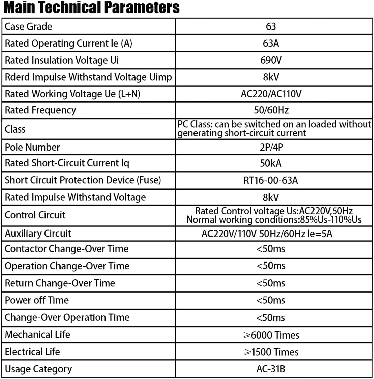
Figure 5: Table detailing the main technical parameters of the ATS, including rated operating current, voltage, frequency, mechanical life, and electrical life.
| Parameter | Value |
|---|---|
| Case Grade | 63 |
| Rated Operating Current Ie (A) | 63A |
| Rated Insulation Voltage Ui | 690V |
| Rated Impulse Withstand Voltage Uimp | 8kV |
| Rated Working Voltage Ue (L+N) | AC220V |
| Rated Frequency | 50/60Hz |
| Class | PC Class: can be switched on an unloaded circuit without generating short-circuit current |
| Pole Number | 2P |
| Rated Short-Circuit Current Iq | 50kA |
| Short Circuit Protection Device (Fuse) | RT16-00-63A |
| Rated Impulse Withstand Voltage | 8kV |
| Control Circuit | Rated Control voltage Us: AC220V, 50Hz. Normal working conditions: 85%Us-110%Us |
| Auxiliary Circuit | AC220V/110V 50Hz/60Hz Ie=5A |
| Contactor Change-Over Time | <50ms |
| Operation Change-Over Time | <50ms |
| Return Change-Over Time | <50ms |
| Power off Time | <50ms |
| Change-Over Operation Time | <50ms |
| Mechanical Life | ≥6000 Times |
| Electrical Life | ≥1500 Times |
| Usage Category | AC-31B |
7. Troubleshooting
If you encounter issues with your ATS, consider the following common problems and solutions:
- No Power to Load:
- Check if both power sources (Source I and Source II) are active.
- Verify all wiring connections are secure and correct.
- Ensure the ATS is in "AUTO" mode for automatic transfer, or manually switch if in "MANU" mode.
- Check for tripped circuit breakers upstream of the ATS.
- Switch Not Transferring Automatically:
- Confirm the ATS is set to "AUTO" mode.
- Check if the control circuit voltage is within the specified range (85%Us-110%Us).
- Ensure both power sources are properly detected by the ATS (check indicator lights).
- Overheating:
- Verify that the load current does not exceed the rated current of 63A.
- Check for loose connections, which can cause resistance and heat.
- Ensure adequate ventilation around the ATS.
For persistent issues, contact a qualified electrician or the manufacturer's support.
8. Maintenance
Regular maintenance helps ensure the longevity and reliable operation of your ATS.
- Periodic Inspection: Annually inspect the ATS for any signs of physical damage, discoloration from overheating, or loose connections.
- Cleaning: Keep the device free from dust and debris. Use a dry, soft cloth for cleaning. Do not use liquid cleaners.
- Terminal Tightness: Periodically check and re-tighten all terminal screws to the specified torque (3.0 N.m for M5 screws) to prevent arcing and ensure good electrical contact.
- Functionality Test: Periodically test the automatic transfer function by simulating a power failure on one of the sources (if safely possible and permitted by local regulations).
9. Warranty and Support
For warranty information, technical support, or service inquiries, please refer to the documentation provided with your purchase or contact your seller directly. Ensure you have your product model and purchase date available when contacting support.