1. Introduction
The ATUUKOPC SK120X is a versatile DC adjustable voltage regulator and charging module designed for various applications requiring precise voltage and current control. It features constant voltage (CV) and constant current (CC) modes, along with Maximum Power Point Tracking (MPPT) for efficient solar charging. The module incorporates a clear LCD display, intuitive controls, and multiple protection mechanisms to ensure safe and reliable operation.
2. Key Features
- Silicone buttons with integrated indicator lights for comfortable and clear operation.
- Professional LCD screen with large, rounded fonts for enhanced readability.
- Immersed gold display board for superior conductivity and durability.
- Robust one-piece injection molded, flame-retardant shell for increased safety.
- Double-layer buckle design ensures secure fixation of the circuit board.
- Supports serial communication via standard Modbus protocol.
- Firmware upgrade capability for future enhancements and new functions.
- Integrated MPPT function for efficient charging, particularly with solar panels.
- High-precision external clock crystal for accurate time, capacity, and energy statistics.
- Powered by a 48-pin MCU controller for fast computing speed.
- Wide input voltage range of 6.0V to 36V.
- Includes input anti-reverse connection and output anti-reverse protection.
- Supports external temperature probe for over-temperature protection.
3. Technical Specifications
| Parameter | Value |
|---|---|
| Input Voltage | 6.0V ~ 36V |
| Output Voltage | 0V ~ 36V |
| Output Current | 0A ~ 6.000A |
| Output Power | 120W (up to 150W with optimal cooling) |
| Voltage Resolution | 0.01V |
| Current Resolution | 0.001A |
| Voltage Accuracy | ±0.5% + 1 word |
| Current Accuracy | ±0.5% + 3 words |
| Conversion Efficiency | Approximately 88% |
| Storage Data Groups | 10 groups |
| MPPT Function | Supported |
| Output Ripple (Typical) | VPP-150mv |
| Buzzer | Yes |
| Soft Start | Yes |
| Input Anti-Reverse Connection | Yes |
| Output Anti-Reverse | Yes |
| Input Undervoltage Protection (UVP) | 5.5V - 36V adjustable (default 5.5V) |
| Output Over-Voltage Protection (OVP) | 0V - 38V adjustable (default 38V) |
| Output Overcurrent Protection (OCP) | 0A - 6.2A adjustable |
4. Product Overview
Familiarize yourself with the components and display of your SK120X module.

Image 1: Front panel with LCD display and control buttons, along with the internal circuit board showing capacitors, inductors, and terminals.

Image 2: Detailed view of the SK120X LCD display, highlighting input voltage (6.0-36V), output voltage (0-36V), output current (0-6.000A), power output (120W), and 10 data storage groups. Also notes support for firmware upgrade, anti-backflow, MPPT solar charging, and Modbus protocol.
5. Setup and Connections
Before operation, ensure all connections are secure and correct to prevent damage to the module or connected devices.
- Input Power Connection: Connect your DC power source (within the 6.0V to 36V range) to the input terminals labeled IN+ and IN-. Observe correct polarity. The module has input anti-reverse connection protection.
- Output Load Connection: Connect your load or rechargeable battery to the output terminals labeled OUT+ and OUT-. When charging batteries, ensure correct polarity. While the module has output anti-reverse protection, reversing battery terminals can still damage the device.
- External Temperature Probe (Optional): For over-temperature protection and optimized battery charging, connect an NTC temperature probe to the designated interface. A battery icon will appear on the display once the probe is successfully connected.
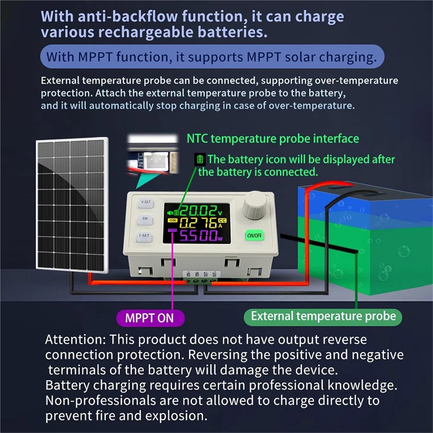
Image 3: Connection diagram illustrating MPPT solar charging with a solar panel and battery, including the external temperature probe connection. Important: This product does not have output reverse connection protection for the battery itself. Reversing battery terminals will damage the device. Battery charging requires professional knowledge; non-professionals should not charge directly without understanding the risks.
6. Operating Instructions
6.1. Basic Controls
- V-SET Button: Press to enter voltage setting mode. Use the rotary encoder to adjust the desired output voltage.
- I-SET Button: Press to enter current setting mode. Use the rotary encoder to adjust the desired output current limit.
- SW Button: Briefly press to switch between different display modes on the main interface, such as input voltage and output voltage.
- ON/OFF Button: Press to toggle the output power on or off. The button will illuminate when the output is active.
- Rotary Encoder: Turn to adjust values when in setting modes (voltage, current). Briefly press the encoder button to confirm selections or cycle through various measurement displays.
6.2. Display Modes
The LCD screen provides various real-time information about the module's operation.
- Input/Output Voltage Display: On the main user interface, briefly press the SW button to switch between displaying the input voltage (indicated by 'IN') and the output voltage.
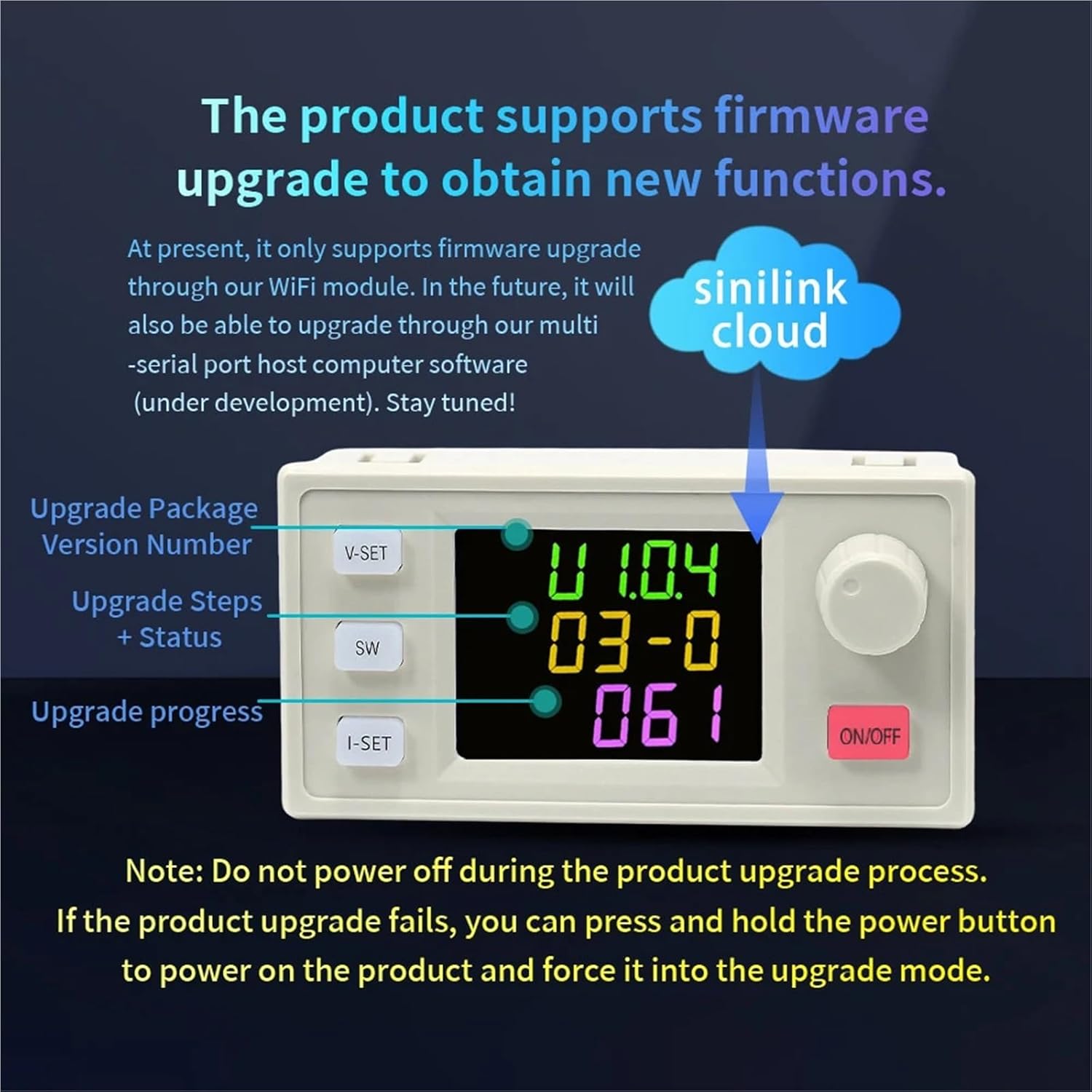
Image 4: Illustration of switching between output voltage display and input voltage display using the SW button.
- Checking Power (W), Capacity (Ah), Energy (Wh), Time (h), Temperature (°C): On the main user interface, briefly press the rotary encoder button to cycle through displaying output power (W), accumulated capacity (Ah), accumulated energy (Wh), elapsed time (h), and external temperature (°C) (if a probe is connected).

Image 5: Illustration of cycling through various measurement displays (power, capacity, energy, time, temperature) by pressing the rotary encoder button.
6.3. Key Lock Function
To prevent accidental changes to the set voltage and current, you can lock the controls:
- Lock: Press and hold the rotary encoder button for 2 seconds. A lock symbol will appear on the display, indicating that settings are protected.
- Unlock: Press and hold the rotary encoder button for 2 seconds again to unlock the controls.
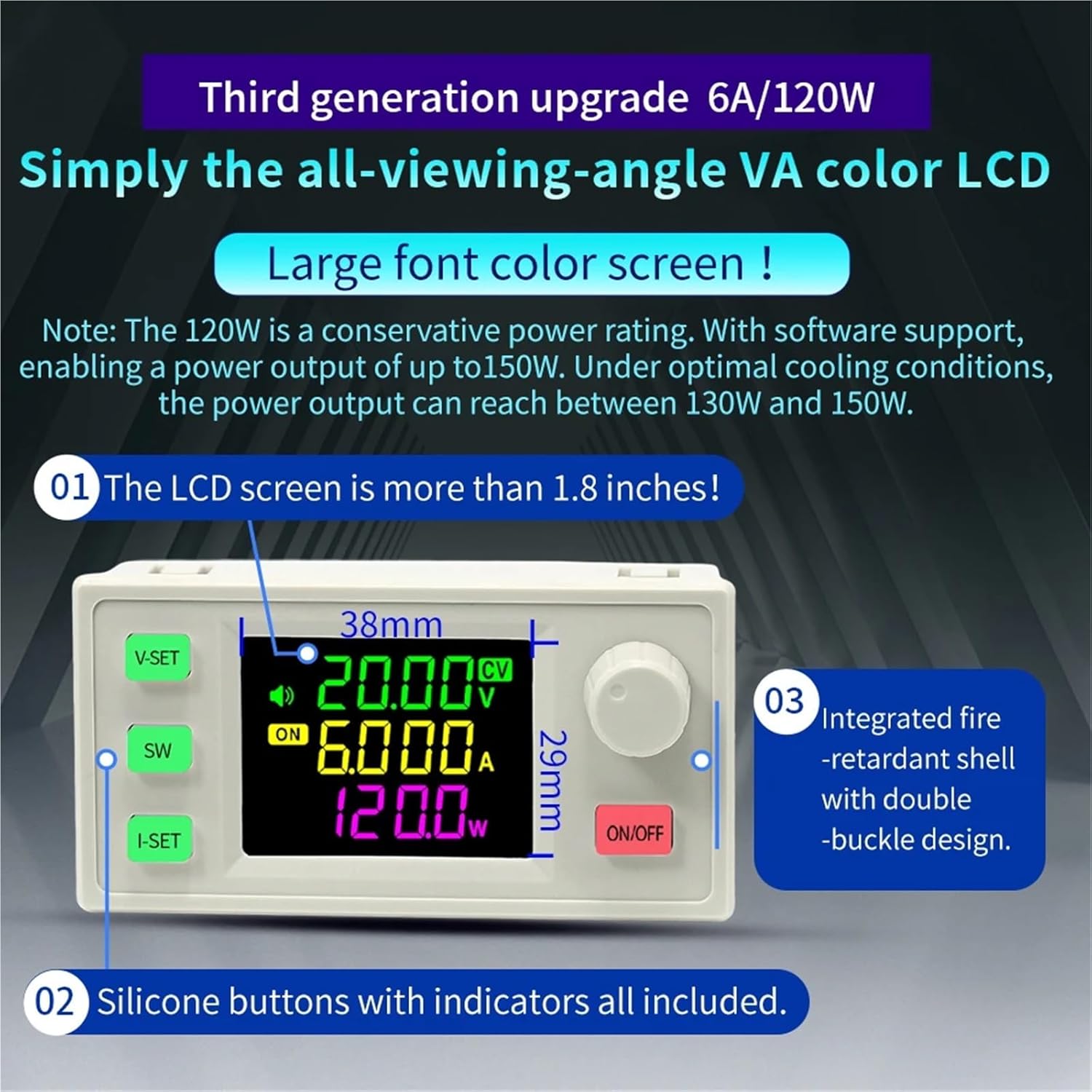
Image 6: Illustration of the key lock function, showing the display with a lock symbol when activated.
6.4. MPPT Charging
The SK120X module supports Maximum Power Point Tracking (MPPT) for efficient charging, particularly when using solar panels. Ensure a solar panel is connected to the input and a compatible rechargeable battery to the output. The MPPT function will automatically optimize the power transfer from the solar panel to the battery, maximizing charging efficiency.
6.5. Firmware Upgrade
The product supports firmware upgrades to obtain new functions and improvements. Currently, upgrades are supported through a dedicated WiFi module. Future updates may include support through multi-serial port host computer software.
- Upgrade Process: Follow the specific instructions provided with the WiFi module or future software. The display will show the upgrade package version number, upgrade steps, status, and progress during the process.
- Important: Do not power off the device during the firmware upgrade process. If an upgrade fails, you can press and hold the power button to force the device into upgrade mode and attempt the upgrade again.
Image 7: Example display during a firmware upgrade, showing version number, steps, and progress. (Note: This image is illustrative of the display format; the actual upgrade screen may vary slightly).
7. Protection Mechanisms
The SK120X module incorporates several protection features to ensure safe operation:
- Input Anti-Reverse Connection: Protects the module from damage if the input power source is connected with reverse polarity.
- Output Anti-Reverse: Prevents current from flowing back into the module from the load or battery when the output is off.
- Input Undervoltage Protection (UVP): Adjustable from 5.5V to 36V (default 5.5V). The output will shut off if the input voltage drops below the set threshold.
- Output Over-Voltage Protection (OVP): Adjustable from 0V to 38V (default 38V). The output will shut off if the output voltage exceeds the set threshold.
- Output Overcurrent Protection (OCP): Adjustable from 0A to 6.2A. The output will shut off if the output current exceeds the set threshold.
- Over-Temperature Protection: When an external temperature probe is connected, the module will monitor temperature and shut off the output if the module or connected battery exceeds a safe operating temperature.
8. Maintenance
Proper maintenance ensures the longevity and reliable performance of your SK120X module:
- Cleanliness: Keep the module clean and free from dust, dirt, and moisture. Use a soft, dry cloth for cleaning.
- Ventilation: Ensure adequate airflow around the module, especially during high power operation, to prevent overheating. Do not obstruct ventilation openings.
- Connections: Periodically check all input and output connections for tightness and signs of corrosion. Loose connections can lead to poor performance or damage.
- Environment: Avoid exposing the module to extreme temperatures, high humidity, or direct sunlight for extended periods.
9. Troubleshooting
If you encounter issues with your SK120X module, refer to the following common problems and solutions:
- No Display/Power:
- Check input power connections for secure contact.
- Ensure the input voltage is within the specified range of 6.0V to 36V.
- Verify that the ON/OFF button is pressed and the module is powered on.
- No Output:
- Confirm that the output is enabled via the ON/OFF button.
- Check the set output voltage and current limits.
- Inspect for active protection mechanisms (UVP, OVP, OCP, Over-temperature). Adjust settings or conditions as needed.
- Incorrect Readings:
- Ensure all connections are tight and free from corrosion.
- Verify the external temperature probe is correctly connected if temperature readings are inaccurate.
- Module Overheating:
- Reduce the load on the module.
- Improve ventilation around the module. Ensure no vents are blocked.
- Check ambient temperature; operate within recommended environmental conditions.
- Battery Charging Issues:
- Double-check battery polarity.
- Ensure the MPPT function is active if using solar charging.
- Verify the external temperature probe connection if used for battery temperature monitoring.
10. Warranty and Support
For warranty information, technical assistance, or any product-related inquiries, please refer to the documentation included with your purchase or contact ATUUKOPC customer service directly. When seeking support, please provide your product model (SK120X) and details of your purchase to facilitate efficient service.