1. Introduction
This manual provides essential information for the installation, operation, and maintenance of the FGJDFD PC1130-1 Printed Circuit Inverter PCB. This component is a critical replacement part designed for Daikin VRV Outdoor Units, specifically compatible with models RXYQ(14.16)T7Y1B, RYMQ(14.16)T7Y1B, and RYYQ(14.16)T7Y1B. It ensures the efficient and reliable operation of your HVAC system's inverter functions.
The PC1130-1 PCB is engineered to meet or exceed original equipment manufacturer (OEM) specifications, providing a durable and precise solution for maintaining your unit's performance.
2. Safety Information
WARNING: Installation and servicing of this Printed Circuit Inverter PCB should only be performed by qualified and certified HVAC technicians. Improper installation or handling can result in electric shock, equipment damage, or personal injury. Always disconnect power to the outdoor unit before beginning any installation or maintenance procedures.
- Ensure all power sources to the Daikin VRV outdoor unit are completely disconnected and locked out before proceeding.
- Wear appropriate personal protective equipment (PPE), including insulated gloves and safety glasses.
- Handle the PCB with care to avoid damage from electrostatic discharge (ESD). Use an anti-static wrist strap.
- Do not touch components marked with "DON'T TOUCH" as shown in image 4, as these may carry high voltage even after power disconnection.
- Verify correct wiring and connections according to the Daikin VRV outdoor unit's service manual.
3. Installation Instructions
This section outlines the general steps for replacing the inverter PCB. Refer to the specific service manual for your Daikin VRV outdoor unit model for detailed, unit-specific instructions.
3.1 Preparation
- Power Disconnection: Ensure the main power supply to the Daikin VRV outdoor unit is completely turned off and secured to prevent accidental re-energization.
- Access Panel Removal: Carefully remove the outdoor unit's access panels to expose the existing inverter PCB.
- Documentation: Take photographs or make diagrams of the existing wiring connections before disconnection to aid in reassembly.
3.2 Removal of Old PCB
- Disconnect Wiring: Carefully disconnect all wiring harnesses and connectors from the old PCB. Note the position of each connector.
- Unmount PCB: Remove the screws or fasteners securing the old PCB to its mounting bracket or chassis. Gently lift and remove the old PCB.
3.3 Installation of New PC1130-1 PCB
- Mount New PCB: Position the new FGJDFD PC1130-1 PCB onto the mounting bracket. Secure it with the appropriate screws or fasteners.
- Connect Wiring: Reconnect all wiring harnesses and connectors to the new PCB, referring to your documentation from step 3.1.3. Ensure all connections are firm and correctly seated.
- Visual Inspection: Perform a thorough visual inspection to ensure no wires are pinched, loose, or incorrectly connected.

Image 1: Top view of the PC1130-1 inverter PCB. This image shows the overall layout of the circuit board, including various components and connectors, mounted on its metal base.
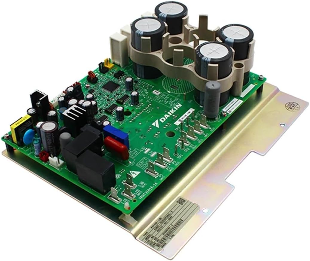
Image 2: Angled view of the PC1130-1 inverter PCB. This perspective highlights the large capacitors and other power components, providing a clearer view of the board's depth and component density.

Image 3: Close-up of specific components and markings on the PC1130-1 PCB. This detailed view shows test points (TP3, TP4, TP5), weight marking (WT 0.8 kg), and other circuit details, including the "PC1130-1(B)" model identifier.
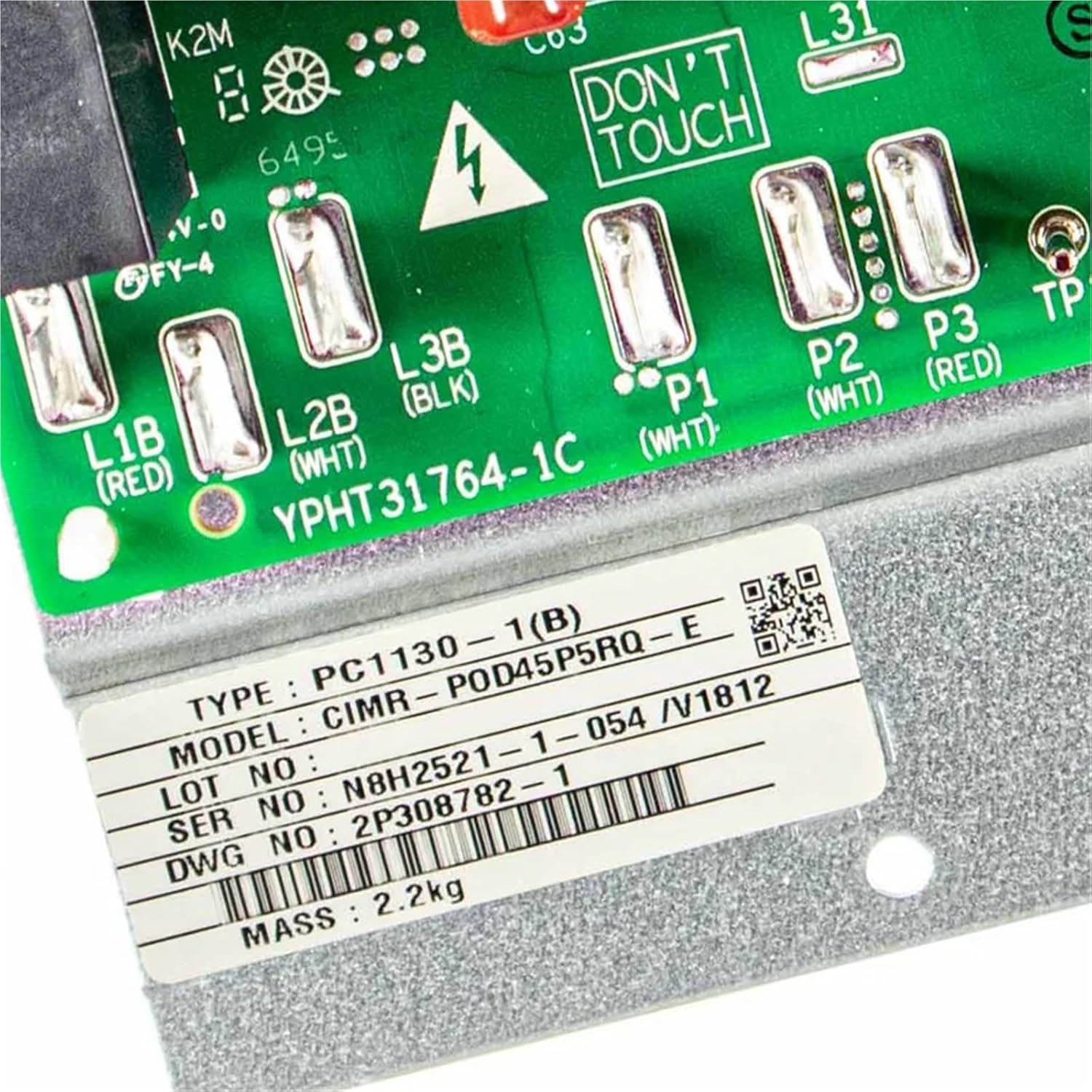
Image 4: Close-up of terminal blocks and a 'DON'T TOUCH' warning on the PC1130-1 PCB. This image highlights critical connection points (L1B, L2B, L3B, P1, P2, P3) and a safety warning, along with a product label showing TYPE: PC1130-1(B), MODEL: CIMR-P0D45P5RQ-E, and other serial information.
4. Operation
The FGJDFD PC1130-1 Printed Circuit Inverter PCB functions as the control center for the inverter compressor within your Daikin VRV outdoor unit. Once correctly installed and the unit is powered on, the PCB will automatically manage the compressor's speed and capacity to meet the system's heating or cooling demands.
- The PCB receives signals from the indoor unit and various sensors within the outdoor unit.
- It processes these signals to regulate the power supply to the compressor, optimizing energy consumption and maintaining desired temperatures.
- No direct user interaction with the PCB is required for its operation. Its function is integral to the automatic control of the VRV system.
After installation, restore power to the outdoor unit. The system should initiate its normal startup sequence. Monitor the unit for proper operation and any error codes.
5. Maintenance
The FGJDFD PC1130-1 Printed Circuit Inverter PCB is designed for long-term reliability and typically requires no routine user maintenance. However, periodic professional inspection of the entire HVAC system, including electrical components, is recommended.
- Professional Inspection: Have a qualified technician inspect the outdoor unit annually. They can check for signs of wear, corrosion, or loose connections on the PCB and other electrical components.
- Cleaning: Ensure the outdoor unit's environment is kept clean and free from debris that could obstruct airflow or accumulate on electrical components. Do not attempt to clean the PCB directly with liquids or abrasive materials.
- Environmental Conditions: Protect the outdoor unit from extreme weather conditions as much as possible, though the PCB is designed for outdoor use within the unit's enclosure.
6. Troubleshooting
If your Daikin VRV outdoor unit experiences issues after replacing the PC1130-1 PCB, consider the following troubleshooting steps. Always ensure power is disconnected before inspecting internal components.
| Problem | Possible Cause | Solution |
|---|---|---|
| Unit does not power on after PCB replacement. | Main power not restored, loose connection, incorrect wiring. | Verify main power supply is on. Check all wiring connections to the PCB for tightness and correctness. Refer to wiring diagrams. |
| Unit powers on but displays an error code related to inverter or compressor. | Incorrect PCB installation, faulty new PCB, or other system component failure. | Double-check all connections. Consult the Daikin VRV service manual for the specific error code. If issues persist, contact a qualified technician. |
| Compressor not running or running erratically. | Wiring issue, sensor malfunction, or PCB fault. | Inspect wiring to the compressor and sensors. Ensure all connectors are fully seated. If the problem continues, professional diagnosis is required. |
For complex issues or persistent problems, it is strongly recommended to contact a certified HVAC technician or Daikin service representative.
7. Specifications
| Feature | Detail |
|---|---|
| Model Number | PC1130-1 |
| Part Number | 5009484 |
| Type | Printed Circuit Inverter Board |
| Application | Daikin VRV Outdoor Units (RXYQ(14.16)T7Y1B, RYMQ(14.16)T7Y1B, RYYQ(14.16)T7Y1B) |
| Brand | FGJDFD |
| Package Dimensions | 1.18 x 0.79 x 0.39 inches |
| Item Weight | 1.76 ounces |
8. Warranty and Support
This product is covered by a standard return policy, typically allowing returns within 30 days of purchase. For specific warranty details, return procedures, or technical support, please refer to the seller's policy or contact the point of purchase.
For further assistance or inquiries, please contact your supplier or a qualified HVAC service provider.