
1. Introduction
This manual provides detailed instructions for the proper setup, operation, and maintenance of the Senzooe ADS1256 24-bit Analog-to-Digital Converter (ADC) module. The ADS1256 is a high-precision, low-noise, 24-bit delta-sigma ADC designed for applications requiring accurate measurement of analog signals. Please read this manual thoroughly before using the module to ensure optimal performance and prevent damage.
2. Product Overview
The Senzooe ADS1256 module is a versatile data acquisition board featuring the Texas Instruments ADS1256 chip. It offers 8 differential or 16 single-ended input channels, a programmable gain amplifier (PGA), and a high data rate output via an SPI interface. This module is ideal for precision measurement applications such as industrial control, medical instrumentation, and scientific research.
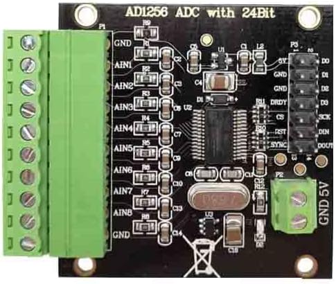
Figure 1: Top view of the ADS1256 module. This image displays the main ADS1256 integrated circuit, the crystal oscillator for precise timing, and other surface-mount components. The green screw terminals for analog inputs and the header pins for digital communication are visible on the left and right sides, respectively.
3. Features
- High Resolution: 24-bit Analog-to-Digital Converter.
- Low Noise: Ensures accurate and stable measurements.
- Multiple Input Channels: Supports 8 differential or 16 single-ended analog inputs.
- Programmable Gain Amplifier (PGA): Allows for amplification of small signals (gains from 1 to 64).
- High Data Rate: Up to 30kSPS (samples per second).
- SPI Interface: Standard serial peripheral interface for easy communication with microcontrollers.
- Onboard Reference Voltage: Provides a stable voltage reference for measurements.
4. Setup
4.1 Physical Connections
Before powering on the module, ensure all connections are made correctly. Refer to the image below for pin identification.

Figure 2: Connection points on the ADS1256 module. The left side features green screw terminals for connecting analog input signals (AIN0-AIN7 and corresponding GNDs). The right side has a header for digital communication, including power (5V, GND) and SPI pins (SCLK, DIN, DOUT, CS, DRDY, RST).
- Power Supply: Connect a stable 5V DC power supply to the 5V and GND pins on the digital header.
- Analog Inputs: Connect your analog signals to the green screw terminals. Use AIN0 through AIN7 for single-ended inputs, or pair them (e.g., AIN0 and AIN1) for differential measurements. Ensure the analog ground (AGND) is properly connected.
- Digital Interface (SPI): Connect the module to your microcontroller using the following SPI pins:
- SCLK: Serial Clock Input
- DIN: Data Input (MOSI)
- DOUT: Data Output (MISO)
- CS: Chip Select (active low)
- DRDY: Data Ready (active low, indicates new conversion data is available)
- RST: Reset (active low)
4.2 Software/Driver Installation
To communicate with the ADS1256 module, you will need to implement an SPI communication protocol on your microcontroller (e.g., Arduino, Raspberry Pi, ESP32). Libraries for the ADS1256 are available for various platforms, which simplify the process of configuring registers and reading data. Consult your microcontroller's documentation and relevant online resources for specific library installation and usage.
5. Operating Instructions
5.1 Initialization
After establishing physical connections, the ADS1256 needs to be initialized via SPI. This typically involves:
- Resetting the Device: Send a reset command or toggle the RST pin.
- Configuring Registers: Set up the desired operating mode, data rate, PGA gain, and input multiplexer settings by writing to the ADS1256's internal registers. Key registers include:
- STATUS: Read device status.
- MUX: Select input channels (e.g., AIN0-AIN1 for differential, AIN0-GND for single-ended).
- ADCON: Configure PGA gain and data rate.
- DRATE: Set the output data rate.
- Self-Calibration: Perform a self-calibration command (e.g.,
SELFCAL) to optimize performance.
5.2 Data Acquisition
Once initialized, the module can begin converting analog signals to digital data.
- Monitor DRDY: Wait for the DRDY pin to go low, indicating that a new conversion result is ready.
- Read Data: Send the
RDATAcommand via SPI to read the 24-bit conversion result. - Process Data: The raw 24-bit value needs to be converted into a meaningful voltage or physical unit based on the reference voltage and PGA gain settings.
- Continuous Conversion: For continuous measurements, repeat steps 1-3.
6. Maintenance
- Cleaning: Keep the module clean and free from dust and debris. Use a soft, dry cloth for cleaning. Avoid using liquids or abrasive cleaners.
- Storage: Store the module in a dry, cool environment, away from direct sunlight and extreme temperatures.
- Electrostatic Discharge (ESD) Protection: Always handle the module with proper ESD precautions to prevent damage to sensitive electronic components. Use an anti-static wrist strap and work on an anti-static mat.
- Connection Integrity: Periodically check all physical connections to ensure they are secure and free from corrosion.
7. Troubleshooting
- No Data or Incorrect Readings:
- Verify all power and SPI connections are correct and secure.
- Check your microcontroller's SPI configuration (mode, clock speed).
- Ensure the ADS1256 registers are configured correctly (MUX, ADCON, DRATE).
- Confirm the analog input signals are within the acceptable voltage range.
- Perform a self-calibration.
- Module Not Responding:
- Check the 5V power supply.
- Ensure the RST pin is not held low.
- Verify the crystal oscillator is functioning (if applicable, check with an oscilloscope).
- DRDY Pin Not Toggling:
- Confirm the module is powered and initialized.
- Check the DRATE register setting; a very low data rate might make toggling less frequent.
8. Specifications
| Specification | Value |
|---|---|
| Brand | Senzooe |
| Item Model Number | 763312647287 |
| Item Weight | 1.06 ounces (30 Grams) |
| Package Dimensions | 3.94 x 3.15 x 0.79 inches |
| ASIN | B0DZHZDMLZ |
| Date First Available | March 6, 2025 |
| Resolution | 24-bit |
9. Warranty and Support
This Senzooe ADS1256 24-bit ADC Module is covered by a standard manufacturer's warranty against defects in materials and workmanship. For specific warranty terms, duration, and to obtain technical support or service, please contact your retailer or the manufacturer directly. Keep your purchase receipt as proof of purchase.
For further assistance, please visit the official Senzooe website or contact their customer support.