1. Introduction
This manual provides essential instructions for the installation, operation, and maintenance of the Auto Engineering C1000A Diesel Generator Governor Speed Controller. Please read this manual thoroughly before installation and operation to ensure proper function and safety.
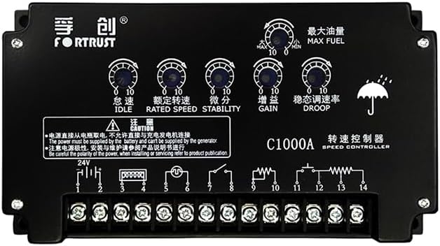
Figure 1: Front view of the C1000A Speed Controller, showing control knobs and terminal block.
2. Safety Information
Always observe the following safety precautions:
- Ensure the power supply is disconnected before installation or maintenance.
- The power must be supplied by the battery and cannot be supplied by the generator.
- Be careful with the polarity of the power. Incorrect wiring can damage the unit.
- Refer to product publications for detailed wiring and servicing information.
- Only qualified personnel should perform installation and servicing.
3. Specifications
| Characteristic | Value |
|---|---|
| Voltage | DC24V (Range 16~32V); DC12V (Special order) |
| Control Frequency | 1000~13000Hz |
| Speed Fluctuation Rate | ≤ 0.25% |
| Stable Speed Regulating | 0~5% (Adjustable) |
| Ambient Temperature | -40°C~+70°C |
| Ambient Humidity | <95% |
| Unit Weight | 0.68kg (approx. 1.5 lbs) |
| Package Dimensions | 6.69 x 6.69 x 3.54 inches |
| Packaged Item Weight | 1.76 pounds |
| Manufacturer | Auto Engineering |
| ASIN | B0DZHB18QP |
| UPC | 602838313422 |
4. Installation
The C1000A speed controller is designed for easy integration into diesel generator systems. Follow these general guidelines for installation:
- Mounting: Securely mount the controller in a location free from excessive vibration, moisture, and extreme temperatures. Ensure adequate ventilation.
- Wiring: Refer to the wiring diagram provided on the unit itself or in the detailed product documentation. Pay close attention to power supply polarity and connections for the actuator, magnetic pickup, and other control inputs/outputs.
- Power Supply: Connect the controller to a DC24V (or DC12V for special orders) battery supply. Do not power the controller directly from the generator output.

Figure 2: Top-down view of the C1000A Speed Controller, highlighting the terminal block and basic wiring instructions printed on the unit.
Important: Incorrect wiring can lead to damage to the controller or the generator system. If unsure, consult a qualified technician.
5. Operation and Adjustment
The C1000A features several adjustable potentiometers for fine-tuning generator speed and stability. These are typically labeled on the unit:
- IDLE: Adjusts the engine idle speed.
- RATED SPEED: Sets the desired operating speed of the generator.
- STABILITY: Controls the response time and stability of the speed control loop. Adjust to minimize speed oscillations.
- GAIN: Determines the sensitivity of the controller to speed changes. Higher gain means faster response but can lead to instability if set too high.
- DROOP: Adjusts the speed droop characteristic, which allows the engine speed to decrease slightly as load increases. This is often used for parallel operation of generators.
- MAX FUEL: Limits the maximum fuel delivery to the engine, affecting maximum power output.

Figure 3: Angled view of the C1000A Speed Controller, clearly showing the labeled adjustment potentiometers for fine-tuning performance.
Adjustment Procedure:
- Start the generator and allow it to warm up.
- Adjust the RATED SPEED potentiometer to achieve the desired operating frequency (e.g., 50Hz or 60Hz).
- Adjust the GAIN and STABILITY potentiometers to achieve stable operation without excessive hunting or oscillations. Start with lower settings and gradually increase until stable.
- If parallel operation is required, adjust the DROOP setting as per system requirements.
- The IDLE and MAX FUEL settings should be adjusted according to engine manufacturer specifications and operational needs.
6. Maintenance
The C1000A speed controller is designed for reliability and requires minimal maintenance. However, periodic checks are recommended:
- Visual Inspection: Regularly inspect the unit for any signs of physical damage, loose connections, or corrosion.
- Cleaning: Keep the controller clean and free from dust and debris. Use a soft, dry cloth for cleaning. Do not use solvents or abrasive cleaners.
- Connection Checks: Ensure all wiring connections are secure and free from wear.
7. Troubleshooting
If the generator experiences speed control issues, consider the following common troubleshooting steps:
| Problem | Possible Cause | Solution |
|---|---|---|
| Generator speed unstable/hunting | Incorrect GAIN or STABILITY settings; faulty magnetic pickup; actuator issues. | Adjust GAIN and STABILITY. Check magnetic pickup for proper signal. Inspect actuator for smooth operation. |
| No speed control/engine runs at max speed | No power to controller; faulty magnetic pickup signal; actuator not responding. | Verify power supply to controller. Check magnetic pickup wiring and signal. Test actuator functionality. |
| Engine speed too low/high | RATED SPEED potentiometer incorrectly set. | Adjust RATED SPEED potentiometer to desired frequency. |
| Controller not powering on | No power supply; incorrect polarity; blown fuse (if applicable). | Check battery connections and voltage. Verify correct polarity. Check for fuses in the power line. |
For persistent issues, contact Auto Engineering technical support or a qualified service professional.
8. Warranty and Support
For warranty information and technical support, please refer to the official product documentation or contact Auto Engineering directly. Ensure you have your product model (C1000A) and purchase details available when seeking support.
Manufacturer: Auto Engineering
ASIN: B0DZHB18QP
UPC: 602838313422