Auto Engineering C2002
C2002 Speed Controller Generator Electronic Governor Speed Control Unit
Model: C2002 | Brand: Auto Engineering
1. Introduction
This manual provides comprehensive instructions for the installation, operation, and maintenance of the Auto Engineering C2002 Speed Controller. The C2002 is an electronic governor speed control unit designed to regulate the speed of generators and other machinery, ensuring stable and efficient performance.
It is crucial to read this manual thoroughly before installation and operation to ensure proper functionality and safety.
2. Key Features
- Robust Construction: Engineered for demanding applications, providing long-term stability in machinery and automotive systems.
- Flexible Installation: Designed for mounting in control boxes or engine peripherals. Vertical installation is recommended in damp or wet environments to prevent moisture accumulation.
- Wide Operating Range: Operates reliably in temperatures from -40℃ to +70℃ and in humidity levels up to 95%, making it suitable for harsh industrial or outdoor conditions.
- Precise Speed Control: Ensures stable operation with a speed fluctuation rate of ≤±0.25% and offers an adjustable 0-5% speed regulation for customized performance.
- Efficient Power Management: Supports dual DC inputs (24V with a range of 18V-32V or 12V with a range of 9V-16V) with ultra-low power consumption (<0.1A, excluding the actuator), ideal for flexible power setups and energy efficiency.
3. Specifications
| Characteristic | Value |
|---|---|
| Battery Voltage | DC24V (Range 18V-32V) or DC12V (Range 9V-16V) |
| Power Consumption | <0.1A (excluding actuator) |
| Speed Fluctuation Rate | ≤±0.25% |
| Stable Speed Regulating | 0-5% (Adjustable) |
| Ambient Temperature | -40℃ to +70℃ |
| Ambient Humidity | <95% |
| Package Dimensions | 6.69 x 6.69 x 3.15 inches |
| Item Weight | 2.64 pounds |
| Manufacturer | Auto Engineering |
| UPC | 602838313408 |
4. Setup and Installation
The C2002 Speed Controller is designed for installation within a control box or securely fixed to other peripheral equipment of the engine. Adhering to the following guidelines will ensure optimal performance and longevity.
4.1 Environmental Considerations
- Temperature: Ensure the installation environment maintains a temperature within the range of -40℃ to +70℃.
- Humidity: The ambient humidity should be less than 95%.
- Air Quality: Install in an environment with dry air. Avoid locations with excessive dust, corrosive gases, or strong vibrations.
- Moisture Protection: If the unit is to be used in a humid or potentially wet environment (e.g., near water), it is strongly recommended to install the speed controller vertically to prevent moisture accumulation and ensure proper drainage.
4.2 Wiring Diagram and Connections
Refer to the labels on the unit for specific terminal connections. Ensure all connections are secure and correctly polarized. Incorrect wiring can damage the unit or connected equipment.

Figure 4.2.1: C2002 Speed Controller Top View. This image displays the top surface of the C2002 Speed Controller, highlighting the terminal block for wiring connections (labeled 1-14), and three adjustment knobs for 'Starting Fuel', 'Speed Ramping', 'Stability', 'Gain', 'Droop', and 'Idle'. The unit is black with white text labels. An umbrella icon indicates suitability for certain environmental conditions.
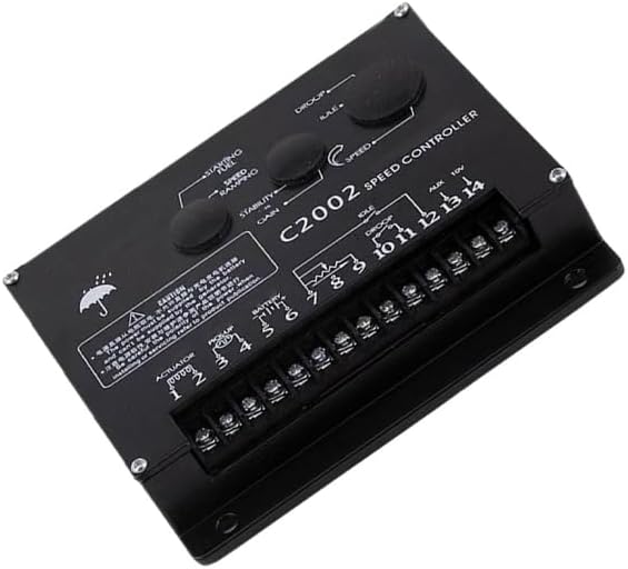
Figure 4.2.2: C2002 Speed Controller Angled View. An angled perspective of the C2002 Speed Controller, providing a clearer view of the terminal connections and the layout of the adjustment potentiometers. This view helps in understanding the physical orientation of the controls and wiring points.
- Power Supply: The power for the controller must be supplied by the battery. It cannot be supplied by the generator. Ensure correct polarity (positive and negative) when connecting the battery. Refer to product documentation for detailed wiring diagrams.
- Actuator Connection: Connect the actuator to the designated terminals (e.g., 1-2).
- Pickup Connection: Connect the speed pickup sensor to the appropriate terminals (e.g., 3-4).
- Battery Connection: Connect the battery power to the designated terminals (e.g., 5-6).
- Auxiliary Connections: Utilize auxiliary terminals (e.g., 7-14) as per your system's requirements for features like droop, idle, or external voltage input.
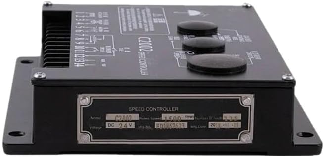
Figure 4.2.3: C2002 Speed Controller Side View with Label. This image shows the side of the speed controller, featuring a metallic label plate. The label provides essential product information such as "Model: C2002", "Voltage: DC 24V", and other manufacturing details, crucial for identification and verification.
5. Operating Instructions
The C2002 Speed Controller features several adjustable parameters to fine-tune the performance of your generator or engine. These adjustments are typically made using potentiometers on the unit's surface.
5.1 Initial Startup and Adjustments
- Starting Fuel: Adjust this knob to control the amount of fuel supplied during engine startup. Proper adjustment ensures smooth and quick engine ignition.
- Speed Ramping: This control dictates the rate at which the engine accelerates to its desired operating speed. Adjust for a smooth transition without overshooting.
- Stability: Fine-tune this setting to achieve optimal engine speed stability, minimizing oscillations or hunting.
- Gain: The gain control affects the responsiveness of the speed controller to changes in engine load. Higher gain means quicker response, but too high can lead to instability.
- Droop: Adjust droop to allow for a slight decrease in engine speed as the load increases. This is often used for parallel operation of generators. The stable speed regulating range is 0-5% and is adjustable.
- Idle: Set the desired idle speed for the engine when no load is applied.
Always make small adjustments and observe the engine's behavior. Consult a qualified technician if you are unsure about any adjustments.
6. Maintenance
The C2002 Speed Controller is designed for durability and requires minimal maintenance. However, regular checks can extend its lifespan and ensure reliable operation.
- Visual Inspection: Periodically inspect the unit for any signs of physical damage, loose connections, or corrosion on the terminals.
- Cleanliness: Keep the unit clean and free from dust, dirt, and moisture. Use a soft, dry cloth for cleaning. Do not use abrasive cleaners or solvents.
- Environmental Check: Ensure the operating environment continues to meet the specified temperature and humidity ranges. Address any issues like excessive moisture or heat immediately.
- Wiring Integrity: Check all wiring connections for tightness and ensure insulation is intact. Loose connections can lead to intermittent operation or damage.
No user-serviceable parts are inside the sealed enclosure. Do not attempt to open the unit, as this will void any warranty and may cause damage.
7. Troubleshooting
This section provides guidance for common issues encountered with the C2002 Speed Controller. For problems not listed here, or if solutions do not resolve the issue, contact qualified service personnel.
| Problem | Possible Cause | Solution |
|---|---|---|
| Engine does not start or starts with difficulty. | Incorrect "Starting Fuel" adjustment. Low battery voltage. Loose or incorrect wiring. | Adjust "Starting Fuel" knob. Check battery voltage and charge if necessary. Verify all wiring connections, especially power supply polarity. |
| Unstable engine speed (hunting/oscillating). | "Stability" or "Gain" settings are incorrect. Issues with speed pickup sensor. | Adjust "Stability" and "Gain" knobs incrementally. Inspect speed pickup sensor and its wiring for damage or loose connections. |
| Engine speed does not reach desired RPM. | "Speed Ramping" or "Gain" set too low. Actuator malfunction. | Increase "Speed Ramping" or "Gain" settings. Check actuator for proper operation and connections. |
| Unit not powering on. | No power supply. Incorrect battery voltage or polarity. | Verify battery connections and voltage. Ensure polarity is correct (DC24V or DC12V). |
8. Warranty and Support
For technical support, service, or warranty inquiries, please contact your authorized Auto Engineering dealer or the point of purchase. Ensure you have your product model (C2002) and UPC (602838313408) available when contacting support.
Optional protection plans may be available for extended coverage. Please refer to your purchase documentation for details on available protection plans, such as 3-Year or 4-Year Protection Plans, or Complete Protect options.
Related Documents - C2002
 |
VEVOR Chocolate Melting Machine User Manual - C2002 Series Official user manual for VEVOR Chocolate Melting Machines (Models C2002-1 to C2002-6). Provides detailed specifications, operating instructions, cleaning and storage guidelines, circuit diagram, and troubleshooting for commercial food warming applications. |
 |
Spektrum Avian ESC Update and Programming Guide Comprehensive guide on how to update and program Spektrum Avian Electronic Speed Controllers (ESCs) using the SmartLink PC App. Covers firmware updates, general settings, throttle control, and governor setup for various Spektrum Avian ESC models. |
 |
Flash on English for Mechanics & Electronics: Answer Key and Transcripts Comprehensive answer key and transcripts for the Flash on English for Mechanics & Electronics course, covering units on materials, manufacturing processes, electricity, electronics, computers, networks, and safety. |
 |
Victron Energy GX Device Generator Integration Guide Comprehensive guide on integrating AC and DC generators with Victron Energy GX devices, covering various controller types like ComAp, CRE Technology, Deep Sea Electronics, DEIF, Fischer Panda, and Hatz. Details setup, configuration, and operation for optimal generator management. |
 |
Basler Auto-Synchronizing Relays: PRS210, PRS220, BE3-25A - Technical Specifications Detailed technical specifications, features, applications, and interconnection diagrams for Basler Electric's Auto-Synchronizing Relays (Models PRS210, PRS220, BE3-25A), designed for precise generator synchronization in power systems. |
 |
PRO-POINT 11,050W Gasoline Generator User Manual | Model 8953135 User manual for the PRO-POINT 11,050W Gasoline Generator (Model 8953135). Covers specifications, safety, operation, assembly, maintenance, and troubleshooting. Essential guide for reliable power generation from Princess Auto Ltd. |