1. Introduction
This manual provides essential information for the safe and efficient operation of your Generic Variable Frequency Drive (VFD). Please read this manual thoroughly before installation, operation, or maintenance to ensure proper use and to prevent personal injury or equipment damage. Keep this manual in a safe place for future reference.
2. Safety Information
WARNING: Electrical shock hazard. Only qualified personnel should install, operate, and maintain this equipment.
- Always disconnect power before working on the VFD or connected equipment. Wait at least 5 minutes after disconnecting power for capacitors to discharge.
- Ensure proper grounding of the VFD and motor.
- Do not operate the VFD with damaged cables or if the enclosure is open.
- Protect the VFD from moisture, dust, and corrosive gases.
- Verify input voltage and phase match the VFD's specifications before connecting power.
- Follow all local and national electrical codes.
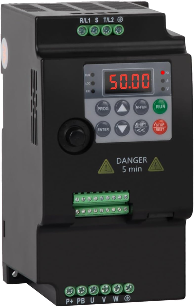
Figure 2.1: Front view of the VFD, showing the digital display, control buttons, and terminal blocks for power input and motor output. A "DANGER 5 min" warning label is visible, indicating the time required for capacitor discharge after power disconnection.
3. Product Overview
The Generic Variable Frequency Drive (VFD) is designed to control the speed and torque of three-phase AC induction motors. It converts fixed-frequency, fixed-voltage AC power into variable-frequency, variable-voltage AC power. This model (5.5KW 380V 3PH-3PH) is specifically designed for a 380V three-phase input and provides a 380V three-phase output, suitable for motors up to 5.5KW (7.5Hp).
Key Features:
- Wide output frequency range (0.1-400Hz).
- Low noise and electromagnetic interference due to PMW control technology.
- Efficient cooling design with multiple ventilation holes for extended service life.
- User-friendly interface for easy operation and parameter setting.
4. Technical Specifications
4.1 General Specifications
| Parameter | Value |
|---|---|
| Model | SU300-5R5G3 (5.5KW 380V 3PH-3PH) |
| Input Voltage | Three-phase 380V AC |
| Output Voltage | Three-phase 380V AC |
| Rated Current | 13A |
| Adapted Motor Power | 5.5KW (7.5Hp) |
| Output Frequency | 0.1 - 400 Hz |
| Item Weight | 1.04 pounds (approx. 0.47 kg) |
| Color | Black |
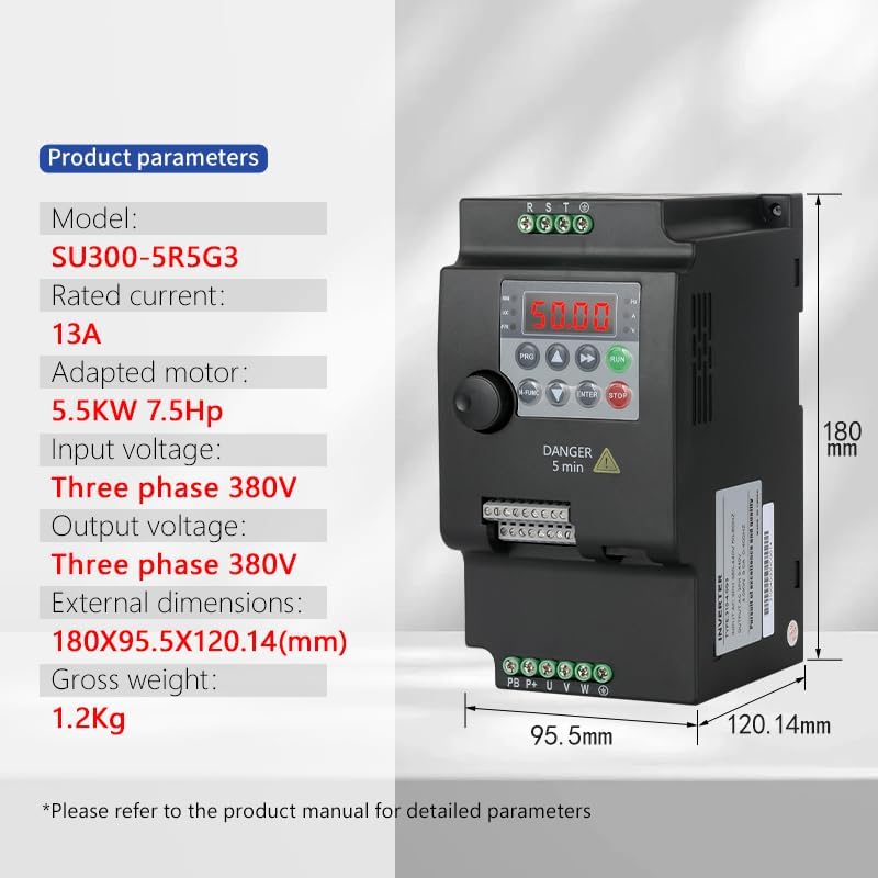
Figure 4.1: Detailed product parameters for the SU300-5R5G3 model, including rated current, adapted motor power, input/output voltage, external dimensions (180x95.5x120.14mm), and gross weight (1.2Kg).
4.2 Dimensions

Figure 4.2: Dimensional drawing comparing two VFD models. The larger model (left) has dimensions of approximately 180mm height, 95.5mm width, and 154mm depth. The smaller model (right) has dimensions of approximately 142mm height, 85mm width, and 116.35mm depth. This manual pertains to the 5.5KW model, which corresponds to the larger unit shown.
5. Installation and Setup
5.1 Mounting
The VFD should be mounted vertically in a well-ventilated area, away from direct sunlight, excessive heat, moisture, dust, and corrosive substances. Ensure sufficient clearance around the unit for proper airflow and heat dissipation.

Figure 5.1: The VFD supports guide rail mounting for easy installation. Align the VFD's mounting clips with the guide rail and press firmly until it clicks into place.
5.2 Wiring
CAUTION: All wiring must be performed by a qualified electrician. Incorrect wiring can lead to severe injury or equipment damage.
Ensure all power is disconnected before beginning any wiring procedures. Use appropriate wire gauges for the VFD's current rating. Connect the input power, motor, and control signals according to the diagrams below.
5.2.1 Three-phase Power Supply Wiring Diagram

Figure 5.2: Wiring diagram for a three-phase 380V input. Connect the R, S, T phases of the power supply to the corresponding input terminals of the VFD. Connect the U, V, W output terminals of the VFD to the motor. Ensure the PE (Protective Earth) terminal is properly grounded. An optional braking resistance can be connected to the P+ and PB terminals.
Note: The diagram also shows a single-phase power supply wiring, but this specific VFD model (5.5KW 380V 3PH-3PH) requires a three-phase 380V input.
5.2.2 Control Terminal Connections
The VFD provides various control terminals for external control signals. Refer to the detailed manual for specific parameter settings related to these terminals.
- S1-S5/Y: Digital input terminals for various control functions (e.g., Run/Stop, Multi-speed selection).
- AO: Analog output terminal.
- AI: Analog input terminal (e.g., for speed reference from a potentiometer).
- 485: RS485 communication interface for remote control and monitoring.
- 24V, GND: Power supply for control circuits.
6. Operation
6.1 Control Panel Overview
The VFD features a digital display and a keypad for local operation and parameter setting.
- Display: Shows frequency, current, voltage, and other operational parameters.
- PROG: Enters/exits parameter setting mode.
- M-FUN: Multi-function key, often used for quick access to common functions or display switching.
- RUN: Starts the motor.
- STOP/REST: Stops the motor or resets faults.
- ENTER: Confirms parameter settings.
- Arrow Keys (Up/Down/Left/Right): Navigate menus and adjust parameter values.
- SHIFT: Used for shifting digits during parameter input.
6.2 Basic Operation Steps
- Power On: After ensuring all wiring is correct and secure, apply power to the VFD. The display will light up.
- Parameter Setting (if necessary):
- Press PROG to enter parameter setting mode.
- Use arrow keys to navigate to the desired parameter group and parameter.
- Press ENTER to view or modify the parameter value.
- Use arrow keys and SHIFT to adjust the value.
- Press ENTER to save the new value.
- Press PROG to exit parameter setting mode.
- Start Motor: Press the RUN button on the control panel. The motor will accelerate to the set frequency.
- Adjust Speed: Use the Up/Down arrow keys to adjust the output frequency (motor speed) during operation, if configured for keypad control.
- Stop Motor: Press the STOP/REST button. The motor will decelerate and stop.
Refer to the comprehensive parameter manual for detailed descriptions of all parameters and advanced control functions.
7. Maintenance
Regular maintenance helps ensure the longevity and reliable operation of your VFD.
- Cleaning: Periodically clean the VFD's exterior and ventilation openings to prevent dust accumulation, which can hinder cooling. Use a soft, dry cloth. Do not use liquid cleaners.
- Inspection: Regularly inspect wiring connections for tightness and signs of wear or damage. Check for any unusual noises or odors during operation.
- Environmental Conditions: Ensure the operating environment remains within the specified temperature and humidity ranges.
- Fan Check: Verify that the cooling fan (if present) is operating correctly and not obstructed.
WARNING: Always disconnect power and wait for the discharge time (at least 5 minutes) before performing any maintenance or inspection.
8. Troubleshooting
This section provides general guidance for common issues. For detailed fault codes and solutions, refer to the complete VFD parameter manual.
| Problem | Possible Cause | Solution |
|---|---|---|
| VFD does not power on | No input power; Blown fuse; Internal fault. | Check power supply; Replace fuse; Contact technical support. |
| Motor does not run | VFD in stop mode; Incorrect wiring; Motor fault; Parameter error. | Press RUN; Verify wiring; Check motor; Review parameter settings. |
| Overcurrent fault (OC) | Motor overload; Short circuit in motor wiring; Rapid acceleration/deceleration. | Reduce load; Check motor/cables; Adjust acceleration/deceleration times. |
| Overvoltage fault (OV) | Regenerative braking; High input voltage. | Increase deceleration time; Install braking resistor; Check input voltage. |
| Undervoltage fault (UV) | Low input voltage; Power dip. | Check input voltage; Ensure stable power supply. |
9. Warranty and Support
9.1 Warranty Information
This product comes with a 1-year quality after-sales guarantee. Please retain your proof of purchase for warranty claims. The warranty covers defects in materials and workmanship under normal use. It does not cover damage caused by improper installation, misuse, unauthorized modifications, or external factors.
9.2 Technical Support
For technical assistance, troubleshooting beyond this manual, or warranty inquiries, please contact your vendor or the manufacturer's customer service. When contacting support, please have your product model number (5.5KW 380V 3PH-3PH) and purchase details ready.
10. Typical Applications
The Generic VFD is suitable for a wide range of industrial applications requiring variable speed control of three-phase motors. Examples include:
- Pumps and Fans
- Conveyors
- Mixers and Blenders
- Machine Tools (e.g., CNC lathes)
- Textile Machinery (e.g., flat knitting machines)
- Material Handling Equipment (e.g., cranes)

Figure 10.1: Examples of industrial equipment where the VFD can be effectively used for motor speed control, demonstrating its versatility across various sectors.


