1. Introduction
This manual provides detailed instructions for the installation, operation, and maintenance of the Auto Engineering HGM9560 Bus Tie Mains Parallel Unit Generator Controller. The HGM9560 is designed for automatic and manual parallel systems involving gensets and mains power, offering reliable control and monitoring for various power management scenarios.
2. Safety Information
Always observe the following safety precautions to prevent injury or damage to the equipment:
- Ensure all power sources are disconnected before installation or maintenance.
- Installation and wiring should only be performed by qualified personnel.
- Verify correct wiring connections to prevent short circuits or electrical hazards.
- Do not operate the controller in wet or excessively humid environments.
- Refer to local electrical codes and regulations during installation.
3. Product Overview
The HGM9560 controller features a 4.3-inch TFT-LCD display for clear status indication and parameter adjustment. It supports bus-mains parallel operation and includes an RS485 communication interface. The unit is equipped with a powerful 32-bit Microprocessor for precise parameter measurement and control.
3.1 Key Features
- Designed for manual/auto parallel systems with gensets and mains.
- Automatic start/stop and parallel running functions.
- 4.3-inch TFT-LCD graphic display with multi-language interface.
- Multiple running states for parallel operation (fixed active/reactive power, peak lopping, load takeover, no-break return to mains).
- 32-bit Microprocessor for precision parameter measurement and adjustment.
- Parameters configurable via front panel, USB, or RS485 interface.
3.2 Physical Description
The HGM9560 controller is housed in a durable black casing, designed for panel mounting. The front panel includes the LCD display, navigation buttons, and status indicators. The rear panel provides terminal blocks for all necessary electrical connections.
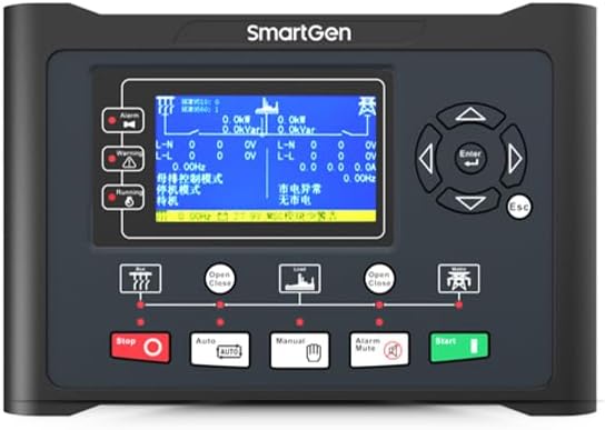
Figure 1: Front view of the HGM9560 controller, showing the LCD display, navigation buttons, and operational indicators.
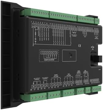
Figure 2: Rear view of the HGM9560 controller, illustrating the various terminal blocks for power, signal, and communication wiring.
4. Setup and Installation
4.1 Mounting
The HGM9560 controller is designed for panel mounting. The installation dimensions are 214mm x 160mm. Ensure adequate space for ventilation and access to wiring terminals.
4.2 Wiring Connections
Refer to the wiring diagram provided on the rear of the unit and in the detailed product documentation for specific connection points. Key connections include:
- Working Power: DC (8-35)V. Connect to a stable DC power supply.
- Mains Voltage Inputs: Connect to the mains power supply for monitoring and parallel operation.
- Genset Voltage Inputs: Connect to the generator output for monitoring and control.
- Current Transformer (CT) Inputs: For current measurement of both mains and genset.
- Auxiliary Inputs/Outputs: For various control and monitoring functions.
- RS485/USB Ports: For PC communication and parameter configuration.
Ensure all connections are secure and correctly polarized. Incorrect wiring can lead to malfunction or damage.
5. Operating Instructions
5.1 Powering On
Once all wiring is complete and verified, apply the DC working power (8-35V). The controller will power on and display the main operational screen.
5.2 Navigation and Display
The 4.3-inch TFT-LCD displays real-time operational data, alarms, and system status. Use the navigation buttons (Up, Down, Left, Right, Enter, Esc) to browse menus, view parameters, and make adjustments.
5.3 Operating Modes
The HGM9560 supports various operating modes, including:
- Manual Mode: Allows direct control over genset start/stop and breaker operations.
- Auto Mode: The controller automatically manages genset start/stop and parallel operations based on configured parameters and system conditions.
- Test Mode: For testing genset functionality without affecting the main load.
5.4 Parallel Running Functions
The controller facilitates parallel operation with mains, offering functions such as:
- Genset output fixed active power and fixed reactive power.
- Mains peak lopping.
- Providing fixed power to mains.
- Load takeover.
- No-break return to mains supply.
5.5 Parameter Configuration
Most parameters can be configured directly from the front panel using the navigation buttons. For advanced configuration and detailed settings, connect the controller to a PC via the USB interface or RS485 port and use the dedicated software.
6. Maintenance
Regular maintenance ensures optimal performance and longevity of the HGM9560 controller:
- Keep the controller clean and free from dust and debris.
- Periodically check all wiring connections for tightness and signs of corrosion.
- Ensure the operating environment remains within specified temperature and humidity ranges.
- Regularly back up configuration parameters, especially after making significant changes.
- Inspect for any physical damage to the casing or display.
7. Troubleshooting
This section provides general guidance for common issues. For complex problems, consult a qualified technician.
| Problem | Possible Cause | Solution |
|---|---|---|
| Controller does not power on | No DC power supply; Incorrect wiring; Blown fuse | Check DC power input (8-35V); Verify wiring connections; Inspect and replace fuse if necessary |
| Genset fails to start | Low fuel; Low battery; Engine fault; Incorrect start parameters | Check fuel level and battery voltage; Address engine issues; Review and adjust start parameters |
| Parallel operation issues | Mains/Genset voltage/frequency mismatch; Incorrect synchronization parameters | Verify voltage and frequency settings; Adjust synchronization parameters; Check CT connections |
| Display shows error message | Sensor fault; Communication error; Internal fault | Note the error code and consult the detailed fault list in the full technical manual; Check sensor connections; Restart controller |
8. Specifications
| Feature | Specification |
|---|---|
| Model | HGM9560 |
| Display | 4.3 inches TFT-LCD |
| Working Power Range | DC (8-35)V |
| Overall Dimension | 266mm x 182mm x 45mm |
| Installation Dimension | 214mm x 160mm |
| Working Temperature | (-25~+70)℃ |
| Weight | 0.95kg (2.09 lbs) |
| Communication | RS485, USB |
| Included Components | 1X controller |
| Manufacturer | Auto Engineering |
9. Warranty and Support
For warranty information and technical support, please refer to the documentation provided with your purchase or contact Auto Engineering customer service. Keep your purchase receipt for warranty claims.